


INSTALLATION
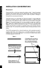
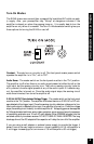
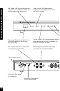
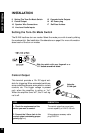
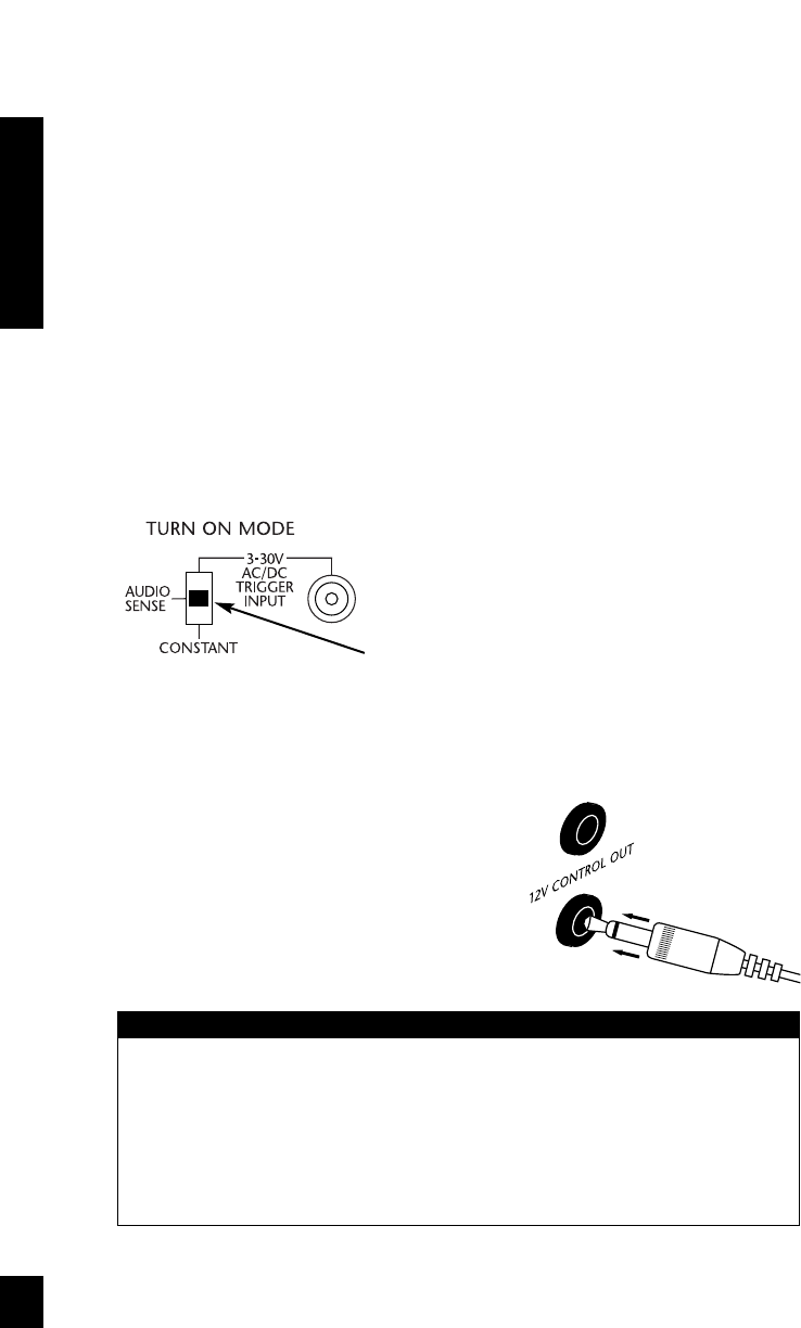
Setting the Turn-On Mode Switch
The SI-245 has three turn-on modes. Select the mode you wish to use by sliding
the mode switch. See Installation Considerations on page 6 for more information
about each of the turn-on modes.
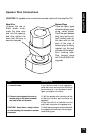
Control Output
This terminal provides a 12v DC signal suit-
able for triggering Niles automated switchers,
some motorized screens, some electric curtain
controls, etc. The trigger voltage is present
only when the amplifier is active or "on".
When the amplifier turns "off", the 12 volt sig-
nal is off.
9 Setting The Turn-On Mode Switch
9 Control Output
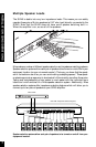
10 Speaker Wire Connections
13 Line Level Audio Inputs
13 Cascade Audio Outputs
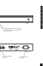
14 AC Power plug
17 Rail Fuse Holders
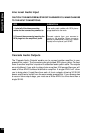
STEP
1. Check the requirements of the
device you want to control.
2. Connect the 3.5mm Jack to the
control output maintaining proper
polarity (tip = +)
DESCRIPTION
The control output has a maximum
current capability of 12vDC 150 mA.
Niles makes an accessory cable
plug FG00724.
Using the
3.5 mm jack.
Slide the switch with your fingernail or a
1/8” slotted screwdriver blade.
11
INSTALLATION