


The SCW-1D is a Decora-
style module designed to
use “Decora-style” face-
plates and mounting hard-
ware. Decora faceplates (up
to 6-gang) with color-
matched plate screws are
available from your Niles
dealer.
P-Ring and Electrical
Boxes
The mounting depth of the
SCW-1D is 2-3/8”. When
installed, the unit extends
1-7/8” behind the sheet-
rock wall (assuming 1/2”
sheetrock). For installation,
you must choose between a
standard light switch plaster
ring (p-ring) or a standard
18 cubic inch (or larger)
electrical box. Suitable p-
rings and electrical boxes
are available from your Niles
dealer or a local electrical
supply company. Using the
p-ring is best because it
gives you unobstructed
access to the full depth of
the wall. In some instances,
the use of a p-ring may be
inappropriate, such as in a
retro-fit (existing construc-
tion) installation, or when
building codes require that
wall devices be enclosed in
electrical boxes. Contact
your local building code
and inspection department
if unsure.
Type of Speaker Wire
For most applications, we
recommend you use 16 or
18 gauge, stranded copper
speaker wire for the SCW-1D
and connections. For wiring
runs longer than 80 feet, 14
gauge wire is recommend-
ed. Using speaker wire larger
than 14 gauge for SCW-1D
and connections is not rec-
ommended — the wire may
not fit into the connectors.
Never use solid-core, alu-
minum or “Romex” type
wire with the SCW-1D.
When running speaker wires
inside walls, most states and
municipalities in the U.S.
specify that you must use a
special type of speaker wire.
Usually, the requirement is
that the wire has a specific
“CL” fire rating, such as
“CL-2” or “CL-3”. Consult
your Niles dealer, building
contractor, or local building
and inspection department
if unsure about which type
of wire is best for your
application.
DO NOT INSTALL THE
SCW-1D INTO ELECTRI-
CAL BOXES WITH 110
VOLT DEVICES.
Some states or municipali-
ties allow devices such as
the SCW-1D to be installed
into the same electrical box
as 110 volt devices, provid-
ed a “low-voltage parti-
tion” is used between the
devices. We do not recom-
mend this. Speaker wires
can act as an “antenna” for
electrical noise. Locating
speaker wires too close to a
light switch or dimmer may
cause a “popping” or
“buzzing” sound to be
heard through the speak-
ers. If you must locate an
SCW-1D near electrical
devices, install it in a sepa-
rate metal electrical box,
ground the box to the elec-
trical system ground, and
route the speaker wires sev-
eral feet away from the
electrical wiring.
If you are installing the
SCW-1D into an existing
wall, take time to consider
any possible obstructions
which may be hidden inside
the wall, such as wood and
metal studs; electrical, tele-
phone wire or other types
of wiring; plumbing; con-
duit; old wall safes; etc.
1. Install the electrical box or
p-ring in the usual manner.
2. Run all the necessary
wiring to the SCW-1D.
Label the wires for future
reference.
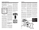
3. Make the connections to
the SCW-1D. Strip 1/4” of
insulation from the end of
each wire. Tightly twist the
end of each wire until there
are no frayed ends. Insert
each wire into the appropri-
ate hole on the connector
blocks; secure the wiring to
the connectors by tighten-
ing the small connector
screws. Be certain that
proper phasing is obser-
ved—connect the positive
terminals on the SCW-1D to
the positive terminals on
the amplifier and speakers;
the negative terminals on
the SCW-1D to the negative
terminals on the amplifier
and speakers. See Figure 1.
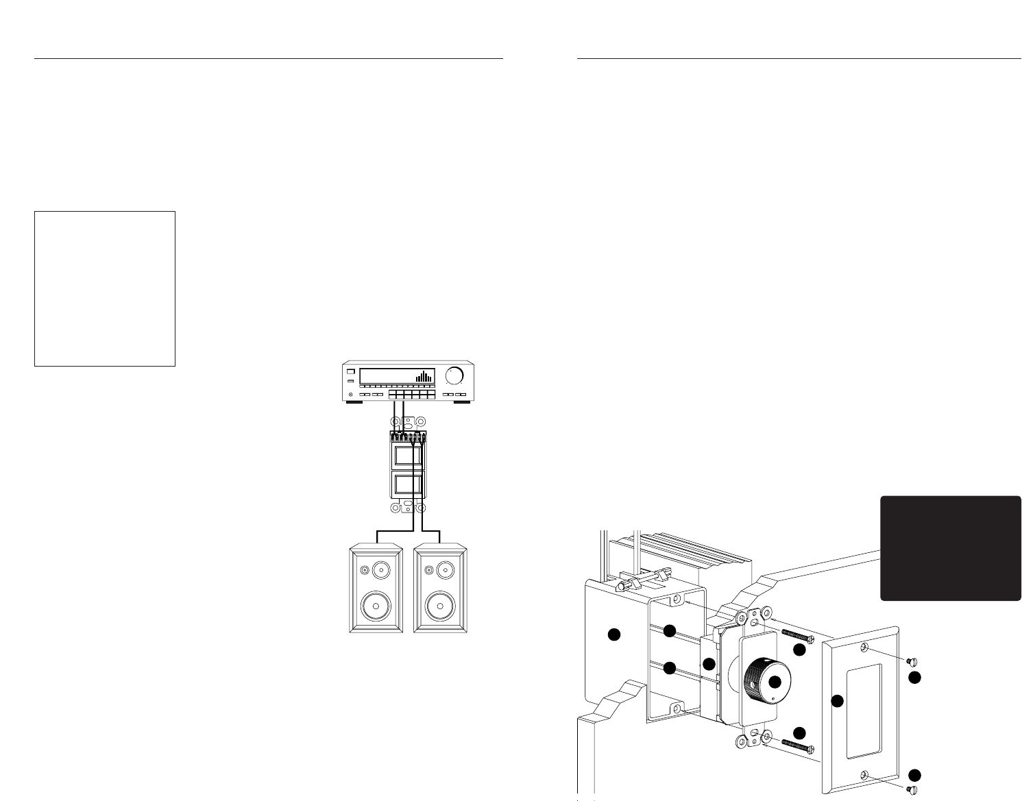
4. Secure the SCW-1D to
the electrical box or p-ring.
Insert the 1-1/4” long device
screws into the oblong-
shaped screw holes on the
top and bottom of the
SCW-1D. Note that the
oblong shape of the screw
holes allow you to position
the SCW-1D so that it is ver-
tical. Position the SCW-1D
so that the screws are
aligned with the threaded
holes in the electrical box or
p-ring. Tighten the screws
using a philips screwdriver.
DO NOT OVER-TIGHTEN. In
some instances, you may
need to loosen these screws
several turns to allow the
SCW-1D to fit flush with the
Decora cover plate.
5. Use the shorter plate
screws to fasten the Decora
faceplate to the SCW-1D.
DO NOT OVER-TIGHTEN
THE PLATE SCREWS OR
YOU MAY DAMAGE THE
FACEPLATE. Line up all the
screws in the same direction
for a finished look. NOTE:
Certain “old work” or
“retro-fit” boxes, such as
the Carlon B225R, have a
plastic “lip” which interferes
with the Decora faceplate
screws. This lip prevents
you from being able to
tighten the screws com-
pletely. To make the clear-
ance necessary for these
screws, you must remove
the parts of the lip causing
interference. There are two
ways to accomplish this:
1. Drill through the lip of
the box at the screw points.
2. Cut notches into the lip
with a pair of diagonal cutters.
Installation Considerations Installation
SCW-1D
Mounting Locations
Convenient mounting loca-
tions for the SCW-1D are:
•
Near entryways or exits
•
Near a desk
•
At your bedside
•
Close to a telephone
•
Near other wall controls
(a) Electrical Box
(b)Speaker Wire
(c) SCW-1D Volume Control
(d) Knob
(e) Device Screws
(f)Decora Faceplate
(g) Faceplate Screws
a
c
e
e
f
d
g
g
b
b
Figure 1
Input
Receiver
Output
Speaker Pair