


15
FINISHING THE INSTALLATION
ADJUSTING THE FEET
The Pro15SW is equipped with four adjustable spike feet that include large slip-on
rubber covers. At the fi nal placement site adjust the feet/spikes as follows:
■ On hard floors (e.g., wood, tile, etc.), check the Pro15SW’s stability and if needed,
adjust the rubber feet one at a time until the cabinet is level.
■ On carpeted floors, tilt the Pro15SW up and remove each rubber cover. Check the
Pro15SW’s stability and if needed, adjust the spikes one at a time until the cabinet
is level.
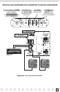
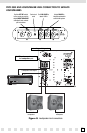
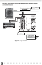
CONNECTING THE PRO15SW
Connect the Pro15SW according to your application (see APPLICATIONS on
page 10). Use high-quality RCA cables for all line-level connections (see CONTROLS
AND CONNECTORS on page 7). For applications with loudspeaker-level connections,
perform the following steps:
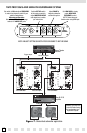
1. At each Pro15SW loudspeaker-level connection, separate the loudspeaker wire so
that at least 2 inches of each conductor are free. Strip away 1/4 inch of insulation
from each loudspeaker wire. Using correct polarity, connect the appropriate
conductor to each five-way binding post.
NOTE: OBSERVE CORRECT POLARITY: POSITIVE (+) GOES TO THE RED POST AND NEGATIVE (–) GOES
TO THE BLACK POST. IF YOU ARE UNSURE OF WIRE POLARITY, SEE THE SECTION,
CHECKING PHASE
ON THE SATELLITE LOUDSPEAKERS
, ON PAGE 16.
2. Connect the other end of the loudspeaker wires to the home theater receiver (or
amplifier) and satellite loudspeakers in the same way.
3. Turn on the home theater receiver and calibrate all loudspeakers in the system
according to the receiver (or surround processor) manufacturer’s instructions.
SETTING UP THE PRO15SW
After making all the connections and calibrating the loudspeakers, set up the
Pro15SW by performing the following steps (see CONTROLS AND CONNECTORS on
page 7 for information on control operation):
1. On the rear panel, set the (Master) POWER switch to ON. Depending on your
application set the (Auto) POWER switch to ALWAYS ON or MUSIC/VOLTAGE SENSE.
2. On the front panel, set the following controls (and switches) to their initial positions:
(CONTINUED ON NEXT PAGE)