


ONE-SPEAKER STEREO MODE VS TWO-SPEAKER STEREO MODE
One-speaker stereo mode has the advantage of covering a larger area than the two-speaker
stereo mode. The trade off between the two configurations is volume. The two-speaker stereo
configurations will be able to play louder in its area than the one-speaker stereo configuration.
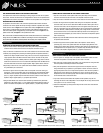
INCORPORATING A VOLUME CONTROL
It is possible to control the volume of the sound at the speaker location. Volume controls are
connected in line with the speaker. An example of wiring an area with 2 speakers and a master
volume control is shown in Figure 2 for one-speaker stereo mode, and Figure 3 for two-speaker
stereo mode. It is usually desirable to control the volume of the speakers in different areas or
zones of the outdoor system. A suggested way to accomplish this is shown in Figure 4 for one-
speaker stereo mode, and Figure 5 for two-speaker stereo mode.
Niles recommends our standard weatherproof volume control, WVC100 series or our weatherproof
muting volume control, WMVC series. In addition to controlling the volume of the loudspeakers,
these controls allow the addition of added speakers without adding more amplifier channels.
INSTALLATION
CONNECTING THE LOUDSPEAKER IN ONE-SPEAKER STEREO MODE
1. Strip two to three inches of each speaker cable’s outer jacket away from the insulated
conductors. Ensure that at least two inches of the separate conductors are free.
2. Strip one half inch of insulation from the end of each conductor for both connection cables.
3. Observe proper phasing when performing the following: Choose the speaker cable that is
labeled for the “Right” amplifier channel. Using a wire nut, connect one stripped end of the
“Right” speaker cable to the PB6Si connection cable’s red wire. The wire nut will protect
the stripped ends of the wire. If added protection is desired, place a large amount of silicon
sealant so the bottom of the wire nut is encased and sealed. Repeat with the PB6Si connec-
tion cable’s black wire and the other stripped amplifier “Right” speaker cable’s conductor.
5. Repeat steps 3 and 4 for the “Left” speaker cable and the PB6Si’s connection cable with
the “yellow/black” pair of conductors.
6. Connect the opposite end of the speaker cables to the amplifier or receiver. Start by per-
forming step 1 and 2 on the speaker cable near the amplifier. Use the cable labeled “Right”
and attach the same conductor you attached to the red loudspeaker wire to the positive
(red) or (+) “Right” amplifier output terminal. Attach the other conductor in that cable to the
amplifier’s “Right” negative (black) or (–) amplifier output terminal.
7. Using the cable labeled “Left” attach the same conductor you attached to the yellow loud-
speaker wire to the positive (red) or (+) “Left” amplifier output terminal. Attach the other con-
ductor in that cable to the amplifier’s “Left” negative (black) or (–) amplifier output terminal.
CONNECTING THE LOUDSPEAKER IN TWO-SPEAKER STEREO MODE
1. Strip two to three inches of each speaker cable’s outer jacket away from the insulated
conductors. Ensure that at least two inches of the separate conductors are free.
2. Strip one half inch of insulation from the end of each conductor for both connection cables.
3. Connect one stripped end of the speaker cable coming from the amplifier to the PB6Si
connection cable’s red wire of one cable and the PB6Si connection cable’s yellow wire. To
connect the three wires, twist the stripped ends of the wire together and screw down the
wire nut on the twisted wires. The material inside the wire nut will protect the stripped ends
of the wire. However, if added protection is desired, place a large amount of silicon sealant
so the bottom of the wire nut is encased and sealed. Pay attention to the markings on the
speaker cable. Each loudspeaker you connect must be connected to the amplifier’s speaker
wire in the same way.
4. Repeat step 3 with the PB6Si connection cable’s black wires and the other stripped ampli-
fier speaker cable’s conductor.
5. Connect the opposite end of the speaker cable to the amplifier or receiver. Start by
performing step 1 and 2 on the speaker cable near the amplifier. Paying attention to the
markings on the speaker cable conductor, attach the same conductor you attached to the
red loudspeaker wire to the positive (red) or (+) amplifier output terminal. Attach the other
conductor to the amplifier’s negative (black) or (–) amplifier output terminal.
TROUBLESHOOTING
VERIFY SYSTEM OPERATION AND LOUDSPEAKER COVERAGE
1. Turn the system “On” and play music to the speakers. Set the Volume controls to a level
that allows the speakers to be easily heard over the “noise” in the area.
2. Verify that music is playing through each speaker. If not, trouble shoot the wiring and make
sure each speaker is electrically connected to the amplifier.
3. Verify that each speaker is connected to the proper channel of the amplifier. To do this,
change the balance of your speakers on your amplifier or receiver so that one channel is
playing loudly and the other is not. Verify that each speaker or each side of the speaker is
attached to the proper channel of the amplifier. If they are not, correct the wiring on the
loudspeaker that is not connected properly. Reset the balance on the amplifier or receiver
so both channels have a similar volume level.
4. If you used a volume control between the amplifier and the speakers, verify that it is
controlling the volume of the loudspeakers in its zone. Repeat this for every volume control
in the system. If it is not, correct the wiring.
5. Position the loudspeakers per the layout and verify that the sound is even and consistent
throughout the area.
Figure 2. One-speaker stereo, one zone volume control wiring
Zone 1
Zone
2
Zone
1
Zone 1
Zone
1
Zone
2
Zone
2
Zone 2
Zone 1
Zone
2
Zone
1
Zone 1
Zone
1
Zone
2
Zone
2
Zone 2
Figure 3. Two-speaker stereo, one zone volume control wiring
Figure 4. One-speaker stereo, two zone volume control wiring
Figure 5. Two-speaker stereo, two zone volume control wiring