


REMOVING THE GRILLE
PAINTING THE SPEAKERS AND GRILLES
INSTALLATION AND OPERATION GUIDE
www.nilesaudio.com
NILES AUDIO CORPORATION
12331 S.W. 130 Street Miami, Florida 33186 Tel: (305) 238-4373 Fax: (305) 238-0185
©2001 Niles Audio Corporation. All Rights Reserved. Niles, the Niles logo, and Blending High Fidelity and Architecture are registered trademarks of
Niles Audio Corporation. MicroPerf is a trademark of Niles Audio Corporation. Kaladex is a registered trademark of DuPont Teijin Films. All other
trademarks are the property of their respective owners. Because we constantly strive to improve our products, Niles reserves the right to change
product specifications without notice. The technical and other information contained herein is not intended to set forth all technical and other speci-
fications of Niles products. Additional information can be obtained on-line. Printed in Taiwan. DS00293ATW
2.Locate the hole template and remove
the inside portion of it (save this part—
it can also be used as a paint mask).
Use the inside of the template to trace
the outlines at the desired location on
the ceiling or wall. With a keyhole
saw, cut along the penciled lines.
BE CAREFUL NOT TO CUT THROUGH
ANY EXISTING WIRING.
3.Attach the speaker wire (CM6.1SI) or
no-strip speaker wire connectors
(CM6.3SI, CM6.5SI and CM8.5SI) to
the speaker. (See Figure 2).
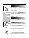
4.There are four clamps which hold the
speaker in place. The clamps are tight-
ened via four front-baffle screws. To
install the speaker, first rotate the
clamps inward. Insert the speaker into
the cutout and tighten the clamps by
turning the screws clockwise. DO NOT
over tighten these screws. Over-tight-
ening the clamps may make the grille
difficult to install (See Figure 3).
NOTE: The screws will be easier to turn
if you “prime” them first. Before
installing the speaker, turn the screws in
and then turn them back out to their
original positions.
5.Install the grille into the speaker. The
grille fits tightly. This is to prevent the
grille from becoming loose over time.
Some effort and care is required when
installing them.
To remove the grille, obtain a small
paper clip (size #1, common) and bend
the last quarter inch of it into an “L”
shape. Holding the paper clip with a pair
of pliers, insert the end with the “L” into
a hole near the edge of the grille.
Remove the grille by pulling the paper
clip towards you.
The Stereo Input loudspeakers may be
painted. The plastic will readily accept
most any kind of paint.
The speaker must be masked prior to
painting them. The inside portion of the
hole template can be used as a paint
mask. Remove the outside portion of the
template by gently pulling along the
perforation. Affix the mask to the front of
the speaker using a piece of tape.
Fold the tape onto itself to form a double-
sided loop. Affix the tape to the tweeter
and place the mask onto the speaker.
The grille should be painted before it is
installed. The best results will be obtained
by using a spray gun or airless sprayer,
thinning the paint (prevents clogging of
grille holes) and by applying several light
coats instead of one heavy one.
INSTALLATION PROCEDURE
CONTINUED
INSTALLATION PROCEDURE
CONTINUED
REMOVING THE GRILLE
PAINTING THE SPEAKERS AND GRILLES
Figure 3
Detail of Mounting System
Figure 2
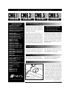
Installing the No-Strip Connector
The CM6.3SI, CM6.5SI and CM8.5SI are
equipped with dual No-Strip Terminals.
Follow this procedure for both left and right
speaker wires.
Separate the speaker wire so that at least
two inches of each conductor are free.
Open the no-strip connector by applying
pressure to the red and black levers until an
audible “click” is heard.
Insert one unstripped wire fully into the
black and one into the red terminal. Pay
attention to the markings on the wire. Each
speaker must be connected to the amplifier
in the same way. Squeeze the red and
black levers until they click signifying that
they have locked into the wire. Check to
make sure that the knife assembly inside
the no strip connector has properly pierced
the wire.