


3. Use a small flathead screw-
driver or your thumbnail to
raise the locking tabs,
exposing the holes on the
removable connector plug.
4. Insert each wire into the
appropriate hole on the
removable connector plug,
and snap the locking
tab down.
NOTE: Maintain proper phas-
ing. Connect the positive
terminals on the volume con-
trol to the positive terminals
on the amplifier and speakers,
and connect the negative terminals on the volume control to
the negative terminals on the amplifier and speakers. To help
you avoid improper phasing, the connector plug is keyed.
Insert the smooth side of the connector plug into the smooth
side of the socket. Don’t force the scalloped side of the con-
nector plug into the smooth side of the socket. See Figure 5.
5. Locate the 2 pin voltage connector (see Figure 7). Strip 1/4"
of insulation from the end of each wire. Tightly twist the end
of each wire until no frayed ends remain and insert each
wire into the appropriate hole on the connector. Use a small
flathead screwdriver to tighten the screws in place.
6. Set the Impedance Magnification Switch (See Figure 6) as
determined by the IM charts (Figures 3 and 4).
7. Plug the connectors into the volume control as shown in
Figure 5. The inputs of the IM volume control are the con-
nector pins labeled AMPLIFIER. The outputs are the connec-
tor pins labeled SPEAKERS.
NOTE: If you reverse these connections, the volume control
won’t function properly .
8. Connect the power-supply wiring between the volume
control and the Niles MVC HUB4 Speaker/ Power Hub.
9. Secure the volume control to the
junction box. Insert the 1-1/4"
device screws into the oblong
screw holes on the top and bottom
of the volume control. The oblong
shape of the screw holes helps you
place the volume control in a
vertical position. Align the screws
with the threaded holes in the
junction box. Tighten the screws
using a Phillips screwdriver. DO
NOT OVERTIGHTEN. If necessary,
loosen these screws several turns so the volume control fits
flush with the faceplate.
MOUNTING LOCATION
WMVC 100: Convenient mounting locations include:
• On a porch or patio wall.
• Near doorways.
• Close to a telephone.
WMVC 100E: Convenient mounting locations include:
• At poolside.
• Near a hot tub.
• Near a barbecue.
Some states or municipalities allow installation of devices such
as the MVC 100 in the same junction box as 110V devices, with
a low-voltage partition between the devices. We do not rec-
ommend this, because speaker wires can act as an antenna for
electrical noise. Locating speaker wires too close to a light
switch or dimmer may cause the speakers to emit a popping or
buzzing sound. If you must locate the IM volume control near
electrical devices, install it in a separate metal junction box,
ground the box to the electrical-system ground, and route the
speaker wires several feet away from the electrical wiring.
PREPARING FOR INSTALLATION
NOTE: The WMVC 100 and WMV 100E require 12VDC
power to operate the muting function of the volume control.
Therefore, two conductor power wire must be run to each vol-
ume control location along with four conductor speaker wire.
WMVC 100: Before you install the WMVC 100 into an exist-
ing wall, consider the possibility of hidden obstructions inside
the wall, such as wood and metal studs; electrical, telephone,
or other wiring; plumbing; and conduit.
1. Install the junction box in the usual manner.
2. Run all necessary wiring to the volume control. Label the
wires for future reference.
WMVC 100E:
1. Run the necessary wiring up through the conduit and the
opening at the base of the enclosure. Label the wires for
future reference.
2. Mount the entire enclosure atop the PVC conduit.
INSTALLATION
1. Locate the 4 pin speaker wire connector plugs (and remove them
if they are plugged in). See Figure 5.
2. Strip 1/4" of insulation from the end of each wire. Tightly
twist the end of each wire until no frayed ends remain.
W EATHERPROOF M UTING S TEREO V OLUME C ONTROLS
65
W EATHERPROOF M UTING S TEREO V OLUME C ONTROLS
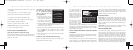
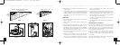
Figure 2
Loosening the
Screws for a Flush Fit
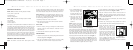
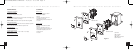
MVC HUB4
Speakers
Receiver
Figure 1
Wiring Diagram
12VDC
DS00318ACN/WMVC100-WMVC100E 11/12/03 10:33 AM Page 7