


Try to line the holes up perfectly, because
it makes pulling the wire much easier. A
good technique is to snap a chalk line
across the face of the studs or against the
bottom of the ceiling joists. Then work
backward so that you can always see the
holes you have already drilled. Paying
careful attention to this will save you a lot
of time later on!
Pulling the Cable
Pull the cable in sections (from the stereo
to the volume control, from the volume
control to the speaker). Start with the
longest sections and use left over wire to
complete the short sections. If you plan to
pull many rooms at the same time through
a central route, walk off the distance to
each destination, add a generous fudge
factor for turns and other obstacles, then
cut off each section so that you have a
bundle of wires you can pull at once.
Whenever you run the wire further than
four and one half feet from a hole in a stud
or joist (open attic space, going up walls,
etc.), fasten the wire to the joists or studs
using cable clamps or appropriately sized
wire staples. The wire should not have
large sags in it, nor should it be too tight.
Try to protect the wire from being stepped
on in attics or other unfinished crawl
spaces. There are guard strips, raceways
and conduits which can be used to protect
the cable. Consult the local building code
for special requirements in your area.
Concealing Speaker Wire
in Existing Walls
This is actually a fairly simple task if you
restrict your choice of speaker locations
and wire routes to the interior walls or
ceilings of your home. Interior walls in
almost all North American residences are
hollow, so that it is easy to flush mount
speakers into them and route new speaker
cable around the house. What you see
when you look at the painted wall board,
plaster, or paneling is only the skin of the
wall. Behind the skin is the skeleton; two-
by-four wood or metal “studs” running
vertically from the floor to the ceiling in
walls and two-by-six or larger “joists” run-
ning horizontally in the ceilings and
floors. In between the studs and the joists
is the space for the wiring and plumbing
of your home.
Exterior walls are different. They must
insulate the house from the heat and cold
outside, so they are stuffed with insulation.
The national building code requires that
the hollow wall space in exterior walls be
broken by a horizontal stud placed
between the vertical studs. This “fire
blocking” makes it very difficult to retrofit
long lengths of wire. In some areas of the
country the exterior walls are constructed
of solid masonry, and have no hollow
space for speakers or wires.
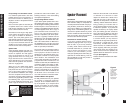
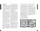
Start by examining all the possible routes
you might take to run the speaker wire
from the speaker to the volume control
and back to the stereo. Use a stud sensor
or other device to locate the internal struc-
ture of the wall. You want to avoid all
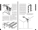
studs or joists. A typical route would be:
from the speaker location in the ceiling,
across the attic, then down through a top
plate (the horizontal 2x4 or 2x6 laid
across the vertical studs) to the volume
control location, back up to the attic,
across the attic, and finally down another
wall plate to a J-Box in the wall behind the
stereo system itself (See Figure 6).
Identify where all of your electrical,
phone, and TV wiring is likely to be and
plan to route around it all. You can acci-
dentally induce 60Hz hum on your speak-
ers if you run your speaker wire right
beside electrical wire for more than a few
feet. Try to keep speaker wire running par-
10
Installation Fundamentals
Installation
Fundamentals
Running the Speaker Wire in New
Construction
If you have doubts about whether you are
capable of installing a Niles ceiling mount
loudspeakers, consult a Niles dealer or
professional installer. They have special
tools, techniques, and experience to make
the impossible possible. The installer can
provide you with an estimate before any
work is done.
Scheduling and Preparation
Plan to schedule the speaker wiring after
the electrical wiring is finished. That way
you can avoid wire routes which could
potentially induce hum over the speaker
wire. The basic rules are:
• Never run speaker wire through the
same hole as an electrical cable.
• Never run speaker wire into the same
J-box as electrical cable.
• Avoid running the speaker wire beside
the electrical cable. Keep your speaker
cable at a distance of at least 18"-22"
from any electrical power cable.
Side-by-side wiring is unavoidable in par-
ticular spots in every house, just move the
speaker wire route away as soon as possi-
ble. If construction forces a side by side
run for more than ten feet, install metal
conduit or shielded speaker wire. Low-
voltage wires such as doorbells, inter-
coms, telephone, security, or television
cannot cause interference or hum on your
speaker wires, so you can safely run all of
them at the same time, through the same
holes, side-by-side.
Before you drill any holes, mount the
speaker brackets in the desired speaker
locations and mount p-rings or open
backed J-boxes where the in-wall volume
controls and stereo equipment will be.
Safety First!
Wear gloves, safety goggles and head pro-
tection when drilling. Avoid nails, they ruin
bits and they can create injury. Pay particu-
lar care when using “hole-hogs” and other
powerful electric drills; the torque of the
drill when suddenly stopped by a nail can
break the wrist of a strong man.
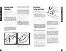
Drilling
Use a bit that is large enough for the wires
you plan to run. An auger bit is the pre-
ferred bit for rough-in wiring. It will actu-
ally pull itself through the wood, so that
the drill motor, not you, does most of the
work. You may be drilling a lot of holes,
so this is an important consideration.
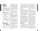
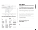
Always drill the holes in the center of the
stud. If you have to notch the stud or drill
the hole closer than one inch from the
edge of the stud, protect the wire with a
nail plate (See Figure 5).
When drilling holes in ceiling joists drill
in the center of the joists and try to locate
the hole near the end of the joist. DO
NOT drill through a “gluelam” or any
load bearing beam without the direction
of your contractor.
9
Installation Fundamentals
Figure 5