


INSTALLATION CONSIDERATIONS
Type of Cable
The AVDA-3 performs best when using
shielded audio and 75 ohm coaxial video
cable. Use low capacitance audio/video
cables for runs that exceed 15 ft. to mini-
mize signal loss. Wire runs greater than 50
ft. are recommended only with cable that
has been specifically designed for such
applications. Contact your cable manufac-
turer for a specific cable recommendation
when wire runs exceed 50 ft.
INSTALLATION LOCATION
The AVDA-3 has been designed for both
shelf and wall mounted installations.
Mounting flanges are provided for wall
mounting while rubber feet enable it to be
placed securely on a shelf. Avoid place-
ment near potential sources of electrical or
radio interference such as lighting controls
and high voltage appliances.
INSTALLATION
Mounting the AVDA-3
Once you have decided on the ideal loca-
tion for the AVDA-3, make sure that the AC
power supply and all signal cables are dis-
connected while mounting. It can be
either mounted on a wall using screws or
placed on shelf using the included adhe-
sive rubber feet (See Figure 1).
Making the Connections
Once the AVDA-3 is securely mounted
follow the steps listed below.
1. Connect the distributed source compo-
nents A/V output signal cables to the
RCA input connectors (L audio, R audio,
and video) (See Figure 2).
2. Connect the AVDA-3’s output RCA con-
nectors to the signal cables leading to
the source signals destination (i.e., the
A/V input of an AM/FM receiver, RF
modulator or television etc.) (See
Figure 2).
3. Connect the included AC power
adapter’s voltage output plug into the
AVDA-3 and then plug its AC power
cord into an unswitched AC outlet.
4. The power LED should be lit solid to
indicate that the AVDA-3 is receiving
power and operating normally.
Note: If your system only requires either
"audio only" or "video only" distribution, the
AVDA-3 can safely operate with either its
audio or its video sections unused.
Termination is not required.
SYSTEM EXPANSION
The AVDA-3 provides a Cascade Out con-
nection for both audio and video. It
enables the connection of additional
AVDA-3’s for further distribution of the
connected A/V source component. As
many as four AVDA-3’s can be connected
together using this feature. Follow the
steps listed below to utilize the Cascade
Output feature.
1. Connect the first AVDA-3 as previously
described in Making the Connections
steps 1 and 2.
2. Connect the Cascade Output connec-
tors of the first AVDA-3 to the RCA input
connectors (left audio, right audio and
video) of the additional AVDA-3 (See
Figure 3).
3. Repeat step 2 using the Cascade
Output of the additional AVDA-3’s to
expand to a maximum of four.
4. Connect the included AC power
adapter’s voltage output plugs into the
AVDA-3’s and then plug their AC power
cords into unswitched AC outlets.
5. The AVDA-3’s power LED’s should be lit
solid to indicate that they are receiving
power and operating normally.
DVD1
FM 105.9
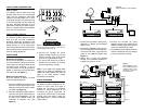
Figure 1 The AVDA-3 can be either mounted on a
wall (A) using screws or placed on shelf using the
included adhesive rubber feet (B).
Figure 2
Typical installation of a single AVDA-3
ZONE 1
ZONE 2
ZONE 3
ZONE 4
ZONE 5
ZONE 6
Figure 3
Typical installation of a two
or more AVDA-3s using the
“Cascade Output” to pro-
vide signal to more than
three components.
DSS
AVDA-3
Home Theater Receiver House Wide Receiver
RF Modulator
Output 1 Output 3
Output 2
DSS
AVDA-3
Zone 1 Receiver
Output 1
AVDA-3
Output 2
Output 3
Zone 2 Receiver
Zone 3 Receiver
Zone 4 Receiver
Zone 5 Receiver
Zone 6 Receiver
Output 1
Output 2
Output 3
Cascade
Output
A
B
Main Input
Main Input
Main Input