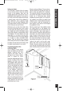
are connected in line with the speaker, so
you must connect the wire from the ampli-
fier to the volume control and then from
the volume control to the speaker.
Speaker Wire
Use 2-conductor speaker wire when con-
necting AT speakers to your receiver or
amplifier. For most applications, we recom-
mend you use a minimum of 16 or 18 gauge
wire. For wiring runs longer than 80 feet we
recommend a minimum of 14 gauge wire.
The gold plated binding post terminals of
the AT speakers will accommodate up to 8
gauge wire directly. Banana jack or pin
connectors may also be used.
When wire is to be run inside walls, spe-
cial jacketing (CL-2 or CL-3) is required to
both protect the wire and for fire preven-
tion. In some areas conduit is required. For
a trouble-free installation, low voltage
wire such as speaker wire must be run in
accordance with the National Electrical
Code and any applicable provisions of the
local building code. If you are unsure of
the correct installation techniques, wire
jacket or type of conduit to use, consult a
professional audio/video installer, your
building contractor, or the local building
and inspection department.
Incorporating a Remote Control
If you are planning to use a stereo system
with a hand held IR remote control, con-
sider the advantages of installing a Niles IR
Repeater System. You are able to control all
of the functions of your system from the
room with the remote pair of speakers.
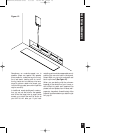
Niles makes a number of IR sensors which
install in the wall, in the ceiling, in cabi-
netry, on tabletops, or even behind the
grille of your Niles AT speakers.
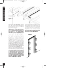
An IR sensor requires that a 2-conductor
shielded wire (West Penn D291 or equiva-
lent) be home run from each sensor loca-
tion to the main equipment location. This
wire is normally run beside the speaker
wire at the same time. Typically, the sensor
is placed in a location that faces your lis-
tening position. Most remote controls will
have an effective line of sight range of 18
to 30 feet with any Niles sensor placed in
a wall, ceiling, on a cabinet or tabletop.
However, when you place a Niles MS-1
MicroSensor behind the perforated alu-
minum grille of a speaker, the sensor’s
effective range is reduced to 9 to 15 feet.
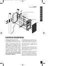
Acoustical Treatment Options
For the best performance from your AT
speakers, acoustically treating the sur-
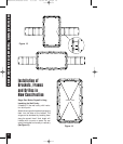
rounding drywall is suggested. In new con-
struction installations, the most practical
option is to block off the wall cavity both
above and below the area where the
speaker will be installed. This will create a
“backbox” containing a specific volume of
air in which the performance of the
AT8500 and AT8700 speakers will be opti-
mized. When installing the AT speakers in
a standard wall (16” stud spacing with 2x4
studs) the suggested air volume would be
2540 cubic inches or 52” of space
between the top and bottom walls of the
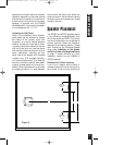
“backbox”. If the speakers are to be
installed in a 2x6 wall, a true backbox may
be constructed using 1/2” or 5/8” thick
Medium Density Fiberboard (MDF). The
dimensions of the enclosure may be varied
in terms of height, width, and depth, as
long as the interior volume of the enclosure
remains approximately 2540 cubic inches.
Although the AT speakers utilize an infinite
baffle design which does not require the
use of a backbox, critical listeners may
Installation Considerations
TECH TIP
Wire size is expressed by its AWG (American Wire
Gauge) number. The lower the number, the larger
the wire, i.e. twelve AWG is physically larger than
fourteen AWG.
4
DS00222A/AT8500-8700 3/1/99 10:47 AM Page 6


