


Connecting The Ten OR Twelve
Caution: Before connecting the Ten OR Twelve to your
audio system, it is important to unplug or turn off all AC
power connections to connected components such as
receivers, amplifiers, preamplifiers, and processors. Do
not plug in or connect the Ten OR Twelve subwoofer to
AC power until all connections have been made.
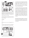
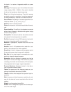
Integrating the Ten or Twelve into your surround system
is simple and straightforward when using this connection
method. Your AV Receiver will control all crossover
functions and the Ten or Twelve will control Subwoofer
gain, phase and boundary equalization.
Connect the Subwoofer/LFE Output on your AV Receiver
to the LFE IN on the back of the Ten or Twelve. (Fig. 2)
In the event your receiver or pre-amp does not have a
LFE or Subwoofer output the Ten/Twelve has two addi-
tional connection methods:
1) Line Level
Use if:
You have an amp or receiver with Pre-Out jacks but no
LFE/Subwoofer jacks.
To connect for a Line Level signal (Fig. 3), keep your
main speakers connected as usual, but use RCA line-
level cables to connect as follows:
• Preamps with Line Out jacks: connect one pair of Line
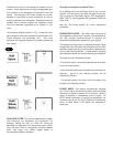
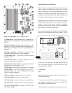
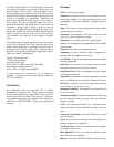
Back of Subwoofer (refer to diagram above)
(1) Power Mode - Leaves Subwoofer in permanantly on
(ON), or puts the subwoofer in automatic standby mode
(AUTO).
(2) Power Indicator - The light is green when the sub-
woofer is on. The light is amber when the subwoofer is in
stand-by mode. The light is red when the subwoofer is in
protection.
(3) Volume Control - Adjusts the loudness of the
subwoofer independently of the main speakers.
(4) Low-Pass Filter - Continuously variable low-pass
crossover control.
(5) Boundary Switch - Selects response mode of
subwoofer, depending on placement.
(6) Subwoofer Phase Selector - 2-position selectable
phase control for subwoofer. (0 - 180)
(7) Line Input - Low level RCA input jacks for L/R signals
(8) LFE In/Out - Low level RCA input jack for LFE or
subwoofer signal. Out is an unbuffered pass through
used for multiple subwoofers.
(9) Hi Level Input - Speaker level input connector.
(10) Power Switch - Turns the unit on and off
(11) Fuse Holder - location of the user servicable fuse
(12) Power Inlet - For universal AC line input connection
(13) Input Voltage Switch - Selects 115 VAC or 230
VAC mains voltage.
115V 60Hz /
230V 50Hz~
300W
115V 60Hz /
230V
50Hz~
300W
T3.0AL 250V
For 115 V
T3.0AL 250V
For
115V
T2.0AL 250V
For 230V
T2.0AL 250V
For
230V
Hi Level Input
Hi Level Input
Out R
In L
LFE
Low Pass
Filter
Low Pass
Filter
40Hz
+L--R+
+ L-- R +
Power
Mode
Power
Mode
On
180
+3dB
-3dB
Auto
0
0
Phase
Boundary
180Hz
Min
Max
Volume
Power
On
Off
Line
Input
Line
Input
Input Voltage
Input Voltage
CAUTION: FOR CONTINUED PROTECTION AGAINST
FIRE, REPLACE ONLY WITH SAME TYPE 250V FUSE
CAUTION: FOR CONTINUED PROTECTION AGAINST
FIRE,
REPLACE ONLY WITH SAME TYPE 250V FUSE
CAUTION
WARNING:
TO REDUCETHERISK OF FIRE OR ELECTRIC
SHOCK,DO NOT EXPOSE THISAPPLIANCE TO RAIN OR MOISTURE.
TO REDUCETHE RISK OF FIRE OR ELECTRIC
SHOCK,
DO NOT EXPOSE THIS APPLIANCE TO RAIN OR MOISTURE.
2001228
WARNING: SHOCK HAZARD-DO NOT OPEN.
AVIS: RISQUE DE CHOC ELECTRIQUE-NE PAS OUVRIR.
WARNING: SHOCK HAZARD-DO NOT OPEN.
AVIS:
RISQUE DE CHOC ELECTRIQUE-NE PASOUVRIR.
RISK OF ELECTRIC SHOCK
DO NOT OPEN
RISK OF ELECTRIC SHOCK
DO
NOT OPEN
CONFORMS TO
ULSTD.6500
CONFORMS TO
ULSTD.6500
CERTIFIED TO
CAN/CSA
STD.E60065
CERTIFIED TO
CAN/CSA
STD.E60065
Green - On
Green - On
Red - Protect
Red - Protect
Amber - Standby
Amber - Standby
115
Powered
Subwoofer
1
6
5
3
4789
2
10
11
12
13
Fig. 2