


SYSTEM CONNECTIONS:
CAUTION: MAKE ALL CONNECTIONS WITH THE AC POWER TURNED OFF!
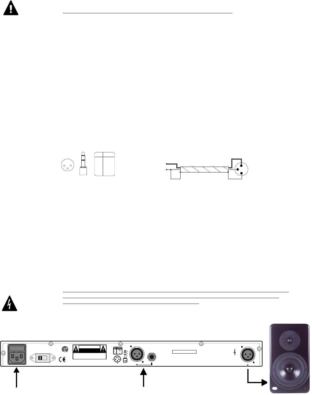
POWER CONNECTIONS/FUSE:
T
CONTROL AMPLIFIER INPUT SECTION:
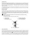
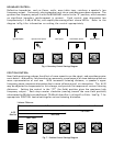
The M-20 Control Amplifier accepts both balanced and unbalanced inputs on either XLR or 1/4” TRS
connectors. These connectors are connected in parallel within the M-20 to allow for convenient equipment
chaining, but only one input should be physically connected to the unit at any time. Figure 3a shows the
proper wiring schematic for each type of connector. Since there are so many different connector types and
signal levels employed by source equipment, some experimentation may be necessary. Keep in mind that
the M-20 can accept a wide range of signals and has an input sensitivity control on the front panel.
SPEAKER CONNECTIONS:
The M-20 includes a 20’ special purpose cable to connect the Control Amplifier to the Monitor. While this cable looks
similar to a standard microphone cable, it is constructed with lower and more consistent conductor impedance.
Portions of the M-20’s crossover circuitry are located in both the amplifier and speaker enclosures, and the cable
supplied is an important part of this electrical network. This allows the speaker cable to function as a neutral and
transparent component in the system. Replacing or extending the supplied cable with any other type will have a
varying and unpredictable impact on the sound. If your installation requires the use of alternative cables, you may
consult the Cable Measurement Data Chart on our website. Be sure they are wired as shown in Fig. 3a.
Using the included cable to connect the M-20 Monitor to the Control Amplifier is quite simple and
straightforward: fit the XLR connectors into the corresponding connectors on the Control Amplifier and
Monitor until the connector locks.
WARNING: IF USING CABLES OTHER THAN THOSE SUPPLIED WITH THIS SYSTEM, BE SURE
THAT NO CONDUCTOR IS WIRED TO THE XLR CASING. FAILURE TO DO SO
MAY CONSTITUTE A RISK OF ELECTRIC SHOCK.
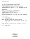
he power cord receptacle contains a spare fuse located within the power connector. To get at the fuse, remove the power
cord and use a small flat head screwdriver to access the fuse compartment. When replacing the fuse with a spare, use only
a fuse of the same current rating. Located next to the power cord receptacle is a voltage selector, preset at the factory for
the destination country; the power cord supplied is appropriate for that voltage. Confirm the voltage selector setting
before powering up the system.
22
33
11
TRSTRS
11
33
22
XLRXLR
PIN SIGNAL PIN SIGNAL
11
22
33
GNDGND
++
__
Fig. 3a Balanced Wiring Diagram
1
2
3
+ (SIGNAL)
- (GND)
Shield
SOURCE
A-20 INPUT
Fig. 3b Unbalanced Wiring Diagram
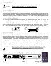
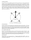
Fig. 4 Typical installation
Source
To AC outlet
To monitor via
supplied red cable
INPUT VOLTAGE
115115
M-20
MONITOR
M-20 MONITOR CONTROL AMPLIFIER.
SERIAL NO:
NHTPro
BENICIA, CALIFORNIA, U.S.A.
MADE IN CHINA G1
CAUTION: CONNECTING OUTPUT
TO ANY PRODUCT OTHER THAN THE
M-20 MONITOR MAY RESULT
IN SEVERE EQUIPMENT DAMAGE.
CAUTION
RISK OF ELECTRIC SHOCK
DO NOT OPEN
WARNING: SHOCK HAZARD - DO NOT OPEN.
AVIS: RISQUE DU CHOC ELECTRONIQUE -
NE PAS OUVRIR.
CAUTION: FOR CONTINUED PROTECTION AGAINST
FIRE REPLACE ONLY WITH SAME TYPE 250V FUSE.
FUSE TYPE:
T9A 250V FOR 110/120V.
T5A 250V FOR 220/240V.
50/60Hz - 950W
INPUT