


10
to fit crimped brass sleeves to the conductors and then solder
the sleeve to the connector. If direct solder connections have to
be made, use a high-temperature solder-pot to tin the tinsel
conductors before making the solder joint to the connector, but
be careful that the nylon thread does not melt. Direct solder
connections can be made to all other cables with free ends (for
cable connection refer to “Wiring Diagram” pages 14-15). On
request, the necessary plugs can be mounted at the factory.
Operation
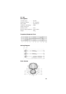
The DT 150 and DT 190 are of a professional standard. It
is important that the external equipment they will be connec
ted
to are of good quality and of the correct impedance and power
ratings to get the best performance from them. Please refer to
the „Technical Specifications“ for detailed information.
The headphone is fully adjustable and should be positioned for
the best fit over the ears. This will give maximum long-term
comfort and will minimise sound leakage or spill.
Convention states that with the DT 190 the boom is placed over
the left ear and the earphones of the DT 190 are identified:
L and R (left and right). The microphone can be used from the
right ear, but if true L and R status should be maintained, or
split feeds are in operation, it may be necessary to make a
custom lead with the headphone connections reversed. The
L&R nomenclature plates of the DT 190 can also be swapped to
reflect these changes.
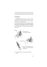
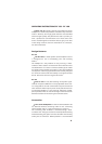
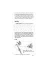
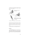
DT 190
1. Lift cap with small screwdriver.
2. Loosen flat screw.
3. Turn disc 180°. Nose of the disc
points to the upper end of the boom
arm.
4. Tighten flat screw and put cap on turning knob.