


XA-300
3
STEREO POWER AMPLIFIER
Date of Purchase ____________________________________
Dealer’s Name ______________________________________
City _______________________________________________
State _____________________ Zip _____________________
Model # ____________________________________________
Serial # ___________________
Offering top power, superior performance and full professional operating features in a roadworthy compact chassis, the XA-300
amplifier is perfect for even the most demanding sound reinforcement installation and touring applications.
FEATURES
TABLE OF CONTENTS
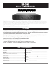
Congratulations on your choice of the NADY AUDIO XA-300 stereo power amplifier — you have purchased one of the finest stereo
amplifiers on the market today. This unit was developed using the expertise of professional sound engineers and working musicians.
You will find that your new XA-300 amplifier has superior performance and greater flexibility than any other amplifiers in its price
range. Please read this manual carefully to get the most out of your new unit.
Thanks for selecting NADY AUDIO as your choice in stereo power amplifiers.
• Full operating features: volume controls; parallel balanced XLR and 1/4" TRS inputs; stereo (dual channel), parallel-input, or bridged
mono operating modes with selector switch; binding post (banana plug) outputs
• Full safety/reliability features: 3 variable speed fans for cooling; soft-start turn on, noise-free on-off; built-in DC offset; independent
DC and thermal overload protection on each channel; short circuit and speaker protection; built-in current limiter
• Power ON and Protect LED’s; Signal and Clipping LED indicators for each channel
• Switching power supply for most reliable operation and lightweight portability
• Roadworthy, rugged double rack space (2U) housing
• ~115(60Hz)/~230V(50Hz) AC select switch and IEC power cord connector with built-in fuse
• XA-300 - 2 x 150W @ 4Ω, Bridged mono: 300W @ 8Ω (2Ω and 4Ω Bridged not recommended)
FEATURES ................................................................................. 3
WARNING ................................................................................... 4
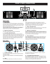
FRONT & REAR PANEL CONNECTIONS ................................ 5
INSTALLATION .......................................................................... 6
CONNECTIONS.......................................................................... 7
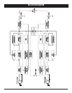
BLOCK DIAGRAM ..................................................................... 9
SPECIFICATIONS .................................................................... 10