


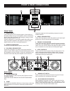

FRONT & REAR CONNECTIONS
5
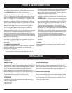
FRONT PANEL
1
6
2
3
4
5
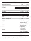
1. POWER SWITCH
To turn the unit ON or OFF, press the upper or lower portion of
this button. Before turning on the amplifier, check all connections
and turn down the level controls. A momentary muting is normal
when turning the amplifier on or off.
(Caution: Always turn on your power amplifier last, after all your
other connected equipment, and always turn off your power
amplifier before your other connected equipment.)
2. POWER LED INDICATORS
These LEDs illuminate when the power is turned “ON”.
3. CLIP (PEAK) LED INDICATORS
These LEDs illuminate if any section of the power amplifier’s
output are within 3DB of clipping. Occasional blinking of the LEDs
are acceptable, but if they remain on more than intermittently you
should turn down either the power amplifier’s level controls or
reduce the output level of the preceding component to avoid
audible distortion.
4. SIGNAL LED INDICATORS
These LEDs illuminate to confirm the presence of an input signal
greater than 100 mV at that channel of the amplifier
5. PROTECT LED INDICATORS
These LEDs illuminate if the power amplifier’s output connection
is shorted or the load impedance is too low. When either of these
LEDs is lit up, turn OFF the power and check the output’s connec-
tion to verify that it is correct, then turn ON the power again.
6. LEVEL CONTROLS
These control the level of signal coming into each channel. The
actual voltage gain of the amplifier is shown in dB. Turn these
controls counterclockwise if the peak LEDs illuminate steadily
(indicating too strong an input signal).
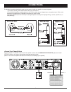
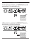
BACK PANEL
14 78 11
10
13 9 12
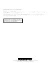
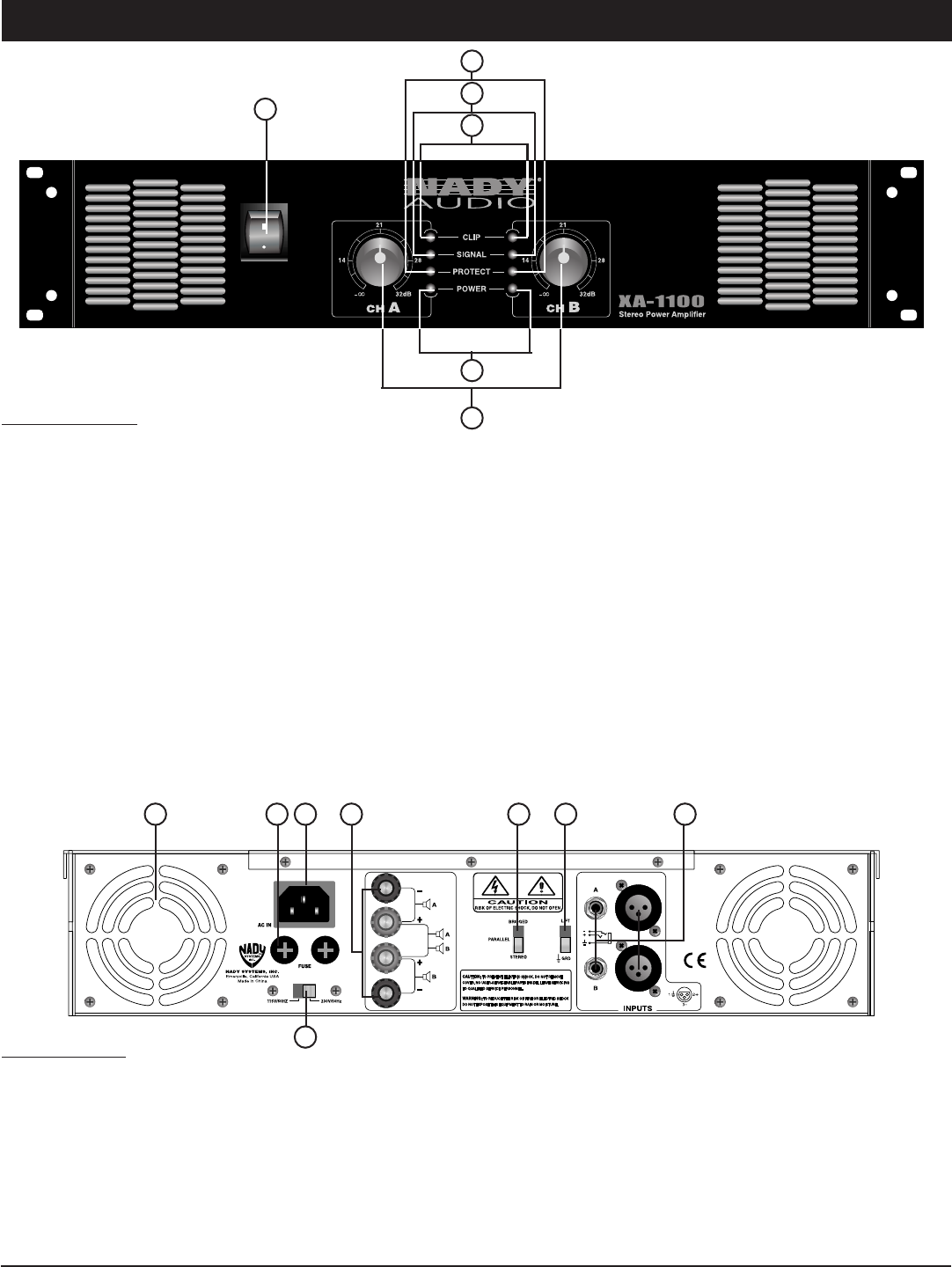
7. POWER CONNECTOR
The cord connector is used to connect the AC power source to
your power amplifier.
(CAUTION: DO NOT REMOVE THE CENTER GROUNDING
PIN.)
8. FUSES
Fuse holders for 20A/250V 3AG fuses. If these fuses continuously
blow, shut off the unit and have it serviced by qualified service
personnel.
9. GROUND LIFT SWITCH
Switch to right to disconnect the chassis from ground if neces-
sary to eliminate hum caused by ground loops.
10. AC VOLTAGE SELECTOR SWITCH
Before plugging in the power cord, check to see that the unit is
set for the proper voltage for your area: ~115V (60Hz) or ~230V
(50Hz). A cover plate is provided to ensure that this switch is not
accidently reset or tampered with between uses.