


6
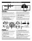
FRONT AND REAR CONTROLS
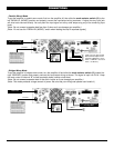
11. BALANCED INPUT CONNECTORS
(1/4” TRS & XLR)
These 1/4” (6.3mm) TRS (Tip/Ring/Sleeve) phone jacks
and XLR jacks are compatible with balanced inputs and
are wired as Tip/Pin 3 = (+), Ring/Pin 2 = (-), and
Sleeve/Pin 1 = Ground. Normal maximum input level at
clipping is 1.15V RMS (+ 4dB). Input impedance is 10K
Ohms. Since the TRS phone jacks and XLR jacks are
wired internally in parallel, you can parallel this unit with
another amplifier by using either the LINE 1/4” jack or the
XLR jack (depending on which you’re using to input your
signal) to output the signal to the input jack of the other
amplifier.
The 1/4” TRS phone jacks can also be used for
unbalanced inputs. For TRS phone plugs, simply connect
the unused side of the balanced input to ground. For 1/4”
TS phone plugs, no change is necessary for compatibility
with this input. Balanced input signals are recommended
as they are less prone to AC hum. For long cable runs a
source of less than 600 ohms output impedance is needed
to avoid signal loss. For short cable runs an unbalanced
signal input should be suitable.
For stereo (two-channel) operation, use the inputs for both
CH-A and CH-B; for parallel or bridged mono operation,
use only CH-A input. (See 13-MODE SELECTOR
SWITCHES below for more explanation.)
12. CLIP LIMITER SWITCH
This switches the internal Clip Limiter ON or OFF for both
channels. The limiter prevents excessive signals from
overloading the amplifier (and thus flattening the peaks of
the waveform and introducing distortion) by automatically
lowering the amplifier gain to minimize overdrive. This
limiting is primarily used to protect full-range speakers
from high frequency distortion or damage to the horns
caused by bass overdrive. However, when driving a
subwoofer, defeating the limiter can produce a desired
extra “punch” to bass instruments, such as kick drums.
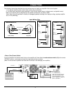
13. MODE SELECTOR SWITCH
The SPA Series amplifiers offer 3 modes of operation:
PARALLEL, STEREO & BRIDGED. Slide the switch to
one of the three positions for you application.
• PARALLEL (MONO) INPUT
—
This mode allows
both channels to operate in parallel with the same
signal and without requiring a Y-cord. In this mode
the inputs for both channels are internally connected,
so that you only need to feed a signal into one of the
channels. This still allows independent control of
each channel. It also enables easy “daisy-chaining”
with other amps by using the other set of input
connectors.
(Note: Do not select this “Parallel” mode when
feeding the amplifier 2 separate signals.)
(Note: Do not use both unbalanced and balanced
cables in the same set-up as that can unbalance all
the connections when daisy-chaining, resulting in
hum.)
• STEREO INPUT — This is the most common
mode generally used, and allows independent
control of 2 separate signals such as stereo
playback, main and monitor live mixes, and bi-amp
operation (highs in one channel and lows in the
other).
• BRIDGED MONO — This mode combines the
power of both channels to drive a single speaker. In
this mode the amp produces 4 times the peak power
and 3 times the sustained power into a 4 or 8 ohm
speaker than each channel can deliver separately in
stereo or parallel mode.
(CAUTION: In this mode the amplifier can deliver
high power into a speaker. Make sure that the
speaker, connectors and wiring can handle this
output. Note that for prolonged overdriven outputs
into a 4 ohm speaker the breaker may trip, so care
must be taken not to overload the amplifier in such
operation.)
Connect the input signal to CH-A input for bridged
mono operation.
14. LF FILTER (30HZ) SWITCH
The low frequency LF filter rolls off frequencies below
30Hz when this switch is turned to the ON position. This
filter improves the audio by limiting unwanted inaudible low
frequency speaker cone movement. Unless a preceding
device, such as a mixer, already has such a 30Hz roll-off,
this filter should generally be employed for optimum audio
and to protect your speaker from excessive cone
excursions beyond its rated limit at sub-audio frequencies.
Generally this switch should only be left “OFF” if you are
monitoring the whole signal for frequency content, such as
for studio playback.
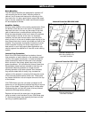
15. FAN
The fan speed is varied continuously automatically to
maintain the proper internal operating temperature. Rear-
to-front airflow keeps amps and racks cool.