


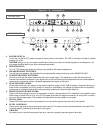
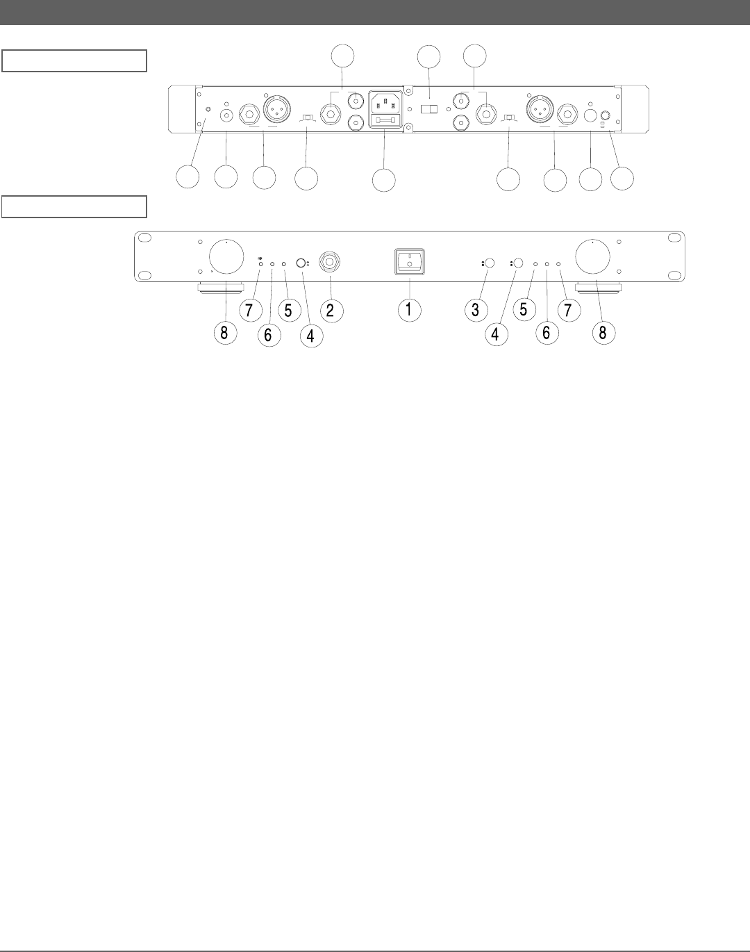
1. POWER SWITCH:
To turn the unit ON or OFF, press the upper or lower portion of this button. The LED in the switch will light to indicate
that the unit is ON.
CAUTION: Always turn on your power amplifier last, after all your other connected equipment, and always turn off
your power amplifier before your other connected equipment.
2. MONITOR JACK:
This 1/4” TRS phone jack allows monitoring of the amplifier with stereo headphones.
3. SPEAKER ON/OFF SWITCHES:
Turn off the main speakers with this switch for private amplifier output monitoring via the MONITOR JACK.
4. SUB FILTER ON/OFF SWITCHES:
Use this to eliminate the lowest frequencies from your output signal. This steep low-cut filter will help eliminate
common low frequency problems in your signal such as hum and other signal components that can cause speaker
rumble and/or resonance, without noticeably degrading the integrity of the audio.
5. PEAK LED INDICATORS:
These LEDs illuminate if any section of the power amplifier’s output is within 3dB of clipping. Occasional blinking of
these LEDs is acceptable, but if they remain on more than intermittently you should turn down either the amplifier’s
level control or reduce the output level of the preceding component to avoid audible distortion.
6. PROTECTION LED INDICATORS:
These LEDs illuminate when the unit is overheated, or when a shorted load or DC is detected in the amplifier output.
When either of these LEDs is lit up, turn OFF the power and check the output’s connection to verify that it is correct,
then turn ON the power again. The amplifier will reset itself when the problem is corrected.
7. SIGNAL LEDS:
These LEDs illuminate to confirm the presence of an input audio signal at that channel of the amplifier.
8. LEVEL CONTROLS:
These control the level of signal coming into each channel. Turn these controls counterclockwise if the peak LEDs
illuminate steadily (indicating too strong an input signal).
9. GROUND:
For safety, and to help eliminate ground loop hum, connect a properly grounded ground wire here.
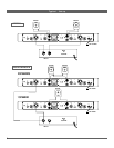
Controls & Connections:
9
11
12
13
16
14
15
14
13
12
11
10
Voltage
240V
120V
Speaker
Output
Mode
Bridged
Stereo
Input
Unbalanced
Input
Balanced
Channel 1
8
4
2
Impedance
Output
Speaker
Channel 2
8
4
2
Impedance
Input
Balanced
Input
Unbalanced
Ground
+
-
+
-
OFF
ON
OFF
ON
H.P.F
OFF
ON
H.P.F
L/MONITOR
POWER
&
POWER
&
PEAKPROTECTSG.INPEAKPROTECT
VOLUME.R
16
18
20
24
28
34
40
50
60
70
0
1
2
3
4
6
8
10
12
-dB
14
VOLUME.L
14
-dB
12
10
8
6
4
3
2
1
0
60
50
40
34
28
24
20
18
16
REAR PANEL
FRONT PANEL
3