


5
CONTROLS AND CONNECTIONS
(1) (2) (5)
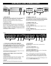
1. POWER SWITCH
Use this switch to power unit ON or OFF. The integrated LED will
light when the unit is ON. Before turning on this unit, verify
connection to the proper voltage AC source, check all
connections and turn down the level controls of equipment
connected to the outputs.
2. MODE DISPLAY LED
The corresponding LED will light green to indicate whether the
SD-2418 is set to Single Mode 1-8 (stereo) or Dual Mode 2-4
(stereo). In Single Mode, the signal input into Ch A is distributed
to outputs 1 through 8. In Dual Mode, the signal input into Ch A
is distributed to outputs 1 through 4 and a signal input into Ch B
is distributed to outputs 5 through 8.
3. CHANNEL A SIGNAL LED
This LED lights green when an audio signal is detected at the
input of Channel A. The LED will light red when the input signal
is too high and causes clipping. If the LED is blinking red, turn
down the volume level of the audio equipment source.
4. CHANNEL B SIGNAL LED
Same operation as Channel A LED
5. LEVEL CHANNELS (1 - 4)
Each control adjusts the Output volume of outputs 1-4 from
–∞ to +6dB.
6. LEVEL CHANNELS (5 - 8)
Each control adjusts the Output volume of outputs 5-8 from
–
∞ to +6dB.
(3) (4)
(6)
(1)(4)(6)
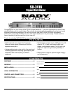
1. FUSE HOLDER & POWER CORD CONNECTOR
This fuse holder contains an AC primary fuse. When this fuse
blows, replace it with the same type fuse, size and power rating
(see SPECIFICATIONS). If it continuously blows, stop replacing
the fuse and refer servicing to qualified personnel. The cord
connector is used to connect the AC power source to your
power amplifier.
(CAUTION: After checking the AC supply voltage, be sure that
the correct fuse is in the fuse holder.)
CAUTION: DO NOT REMOVE THE AC PLUG CENTER
GROUNDING PIN.
2. SELECT SWITCH
This push button switch selects the mode of operation. When
the switch is out, Single Mode 1-8 (mono) is selected.
Depressing this button selects Dual Mode 2-4 (stereo).
3. INPUTS
Channel A and Channel B XLR balanced line level inputs.
4. LINK OUTPUTS
Ch. A and Ch. B XLR outputs linked in parallel with the
respective input.
5. OUTPUT CONNECTORS (1 - 4)
Balanced XLR outputs for Ch. A signal.
6. OUTPUT CONNECTORS (5 - 8)
Balanced XLR outputs for Ch. A signal, when in Single Mode,
and Ch. B signal when in Dual Mode.
Note: All output signals are in-phase with the input signal.
7. INPUT VOLTAGE SELECT SWITCH (BOTTOM PANEL)
Select 115V/60Hz or 230V/50Hz as appropriate for your area.
(CAUTION: Selecting the wrong voltage can damage your unit.
See also POWER CONNECTION, pg 4)
(2) (5) (3)
FRONT
REAR
(3) (4)
(7)
Bottom
Panel