


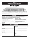
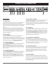
CONTROLS AND CONNECTORS
5
FRONT PANEL
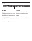
Front Panel
(1) POWER SWITCH
Use this switch to power unit ON or OFF. The integrated LED will
light when the unit is ON. Before turning on this unit, verify
connection to the proper voltage AC source, check all connections
and turn down the level controls of equipment connected to the
outputs.
(Note: The TMP-2 will not output audio for approximately 16
seconds after power up due to the time it takes for the tubes to
warm up. Do not turn up the audio until after this warm up period
to avoid possibly damaging speakers or your hearing due to
improper level settings.)
(2) INPUT CONTROL
The INPUT CONTROL sets the amount of input gain of the
TMP-2, turn the control clockwise to increase gain and
counterclockwise to decrease gain. You may control two ranges of
gain with this control, +26 to +60dB and +6 to +40dB. Selection of
the gain range is made with the +20dB GAIN SWITCH (3)
(3) +20dB GAIN/NORM SWITCH
Use the +20dB GAIN/NORM switch to set the gain range of the
INPUT CONTROL (2). When the switch is out, the TMP-2
operates in Normal mode, depressing the switch adds 20dBs of
gain. For microphone applications, where more level is needed,
push the switch in.
(4) PHANTOM POWER SWITCH
Use the PHANTOM POWER to supply power to all microphones
requiring +48V phantom power. The TMP-2 phantom power is
engaged and disengaged with this switch Phantom power is
applied to pins 2 and 3 of the XLR INPUT (13) jacks when this
switch is pushed in. To disengage phantom power, position the
switch in the out position.
(1)(9)(8)
(5) OUTPUT LEVEL VU METER
The output level of the TMP-2 can be monitored using the analog
OUTPUT LEVEL VU METER. The meter’s 0dB marking
represents +12dB at the XLR output and +6dBu at the 1/4" output.
The output meter will also reflect any attenuation due to the output
limiter when it is engaged.
(6) CLIP/LIMIT LED
The CLIP/LIMIT LED lights green when the unit is powered. The
LED also functions as a clipping and limiting indicator. The LED
lights red when the audio signal reaches 6dB below hard clipping.
If the OUTPUT LIMITER SWITCH (8) is depressed, the LED will
light red when the limiter engages at which point the gain will be
reduced automatically to avoid clipping.
(7) PHASE REVERSE / NORM SWITCH
When the switch is in the Out position of the output signal is
normal. Depressing the switch reverses the phases of the output
signal. In multi-microphone applications, mic placement can affect
the phase of the signals. If your sound is “thin” or “out of position”,
reverse the phase to correct the problem.
(8) OUTPUT LIMITER SWITCH
When this switch is depressed the output level is limited to 0dB for
the 1/4 output and +6dB for the XLR output. This is specially
designed to prevent clipping of the audio waveform. This also
reduces the possibility of overload to any units connected to the
outputs of the TMP-2.
(9) OUTPUT CONTROL
The OUTPUT CONTROL sets the output level of the TMP-2.
When the control is fully counterclockwise the output level of the
TMP-2 is zero. Turning the control clockwise increases the level of
the output to a maximum of +10dB of gain. This gain is in addition
to the existing input gain.
(7)(6)(5)(4)(3)(2)