


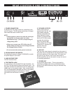
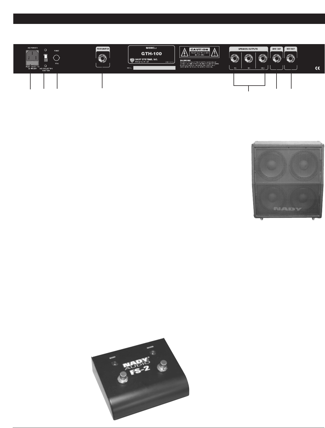
REAR CONTROLS AND CONNECTIONS
6
1. POWER CONNECTION
A standard IEC AC power socket for connecting to the
main AC supply. The IEC power socket has an integral
fuse holder that takes a 20mm fuse.
NOTE:
• Always replace a blown fuse with the same type
as specified on the rear panel and under
Specifications (pg. 7) for the corresponding AC
voltage being used.
• Before you connect your GTH-100 to the AC,
please make sure that your local voltage matches
the Voltage Selector Switch.
• Do not remove the center ground conductor.
2. VOLTAGE SELECTOR SWITCH
For selecting the proper voltage (115/230VAC) to match
the power supply in your area.
3. HIGH VOLTAGE FUSE
1A 250V fast blow fuse
4. FOOTSWITCH JACK
For connecting to the included FS-2 dual footswitch. On
the FS-2, the right switch controls the Reverb on/off. The
left switch controls the Lead Boost on/off for adding up to
12dB of gain at the preamp stage. Note: connecting the
FS-2 will automatically decrease the level at the preamp
input stage allowing it to be boosted to a higher
level when the Lead Boost is switched
on.
5. SPEAKER OUTPUTS
Power output jacks for
connecting to 4Ω, 8Ω, and
16Ω speaker cabinets.
Although compatible with
many cabinets, for best
results it is recommended
that the GTH-100 be used
to power the matching
GAC-412 cabinet (8Ω),
which utilizes (4x) 12” Nady
PowerDrive™ speakers for
optimum tone and
maximum output.
6. LINE OUT
This line level output signal is derived from the output of
the power amp to incorporate all the characteristics, color
and tonal response of the output tubes. This signal can
be input into any device, such as an audio mixer or
another amplifier, and can be useful in many live sound
or recording applications.
7. REVERB OUT
A pure reverb signal output. This may be used for
recording by plugging into mixing consoles/recording
devices or for stereo effects by using an outboard amp
and speaker.
(1)
(2) (3)
(6)
(4)
(5)
(7)