CONTROLS AND CONNECTIONS
[Note: Always reset a channel’s
input Gain (or external devices’
output level) after altering the
amount of mixer equalization
cut or boost applied.]
The key to successful equaliza-
tion is to avoid excess. Too
much equalization on the input
channels will result in a mix
that is smeared together with
nothing specifically defined.
During rehearsals, experiment
with the equalizer controls on
various instruments, vocals and
combinations of these mixed
together to become familiar
with various equalizer settings.
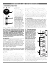
(6) AUX SEND 1, 2 CON-
TROLS
Both Aux Sends are mono and
post-EQ and control the level
of the signals sent to the AUX
buses.
• Aux Send 1 is pre-fader
and the signal sent to the
AUX 1 bus will be unaffect-
ed by the channel fader
setting.
• Aux Send 2 is post-fader
and the signal level sent to
the AUX 2 bus will be
affected by the channel
fader setting.
For almost all effects send pur-
poses, you will want to use the
post-fader AUX 2, so that when
a fader level is adjusted, any
reverb send from that channel follows the fader. Otherwise,
when the fader is pulled down, the reverb from that channel
would still be audible. Most reverbs etc. internally sum the left
and right inputs so that you can use AUX 2. You can also use
this AUX 2 send to feed inputs to a multi-track recorder or any
other unbalanced line level application. On the other hand, for
cueing purposes and monitor amplifiers, use the pre-fader
AUX 1 (i.e. independent of the channel fader)
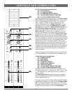
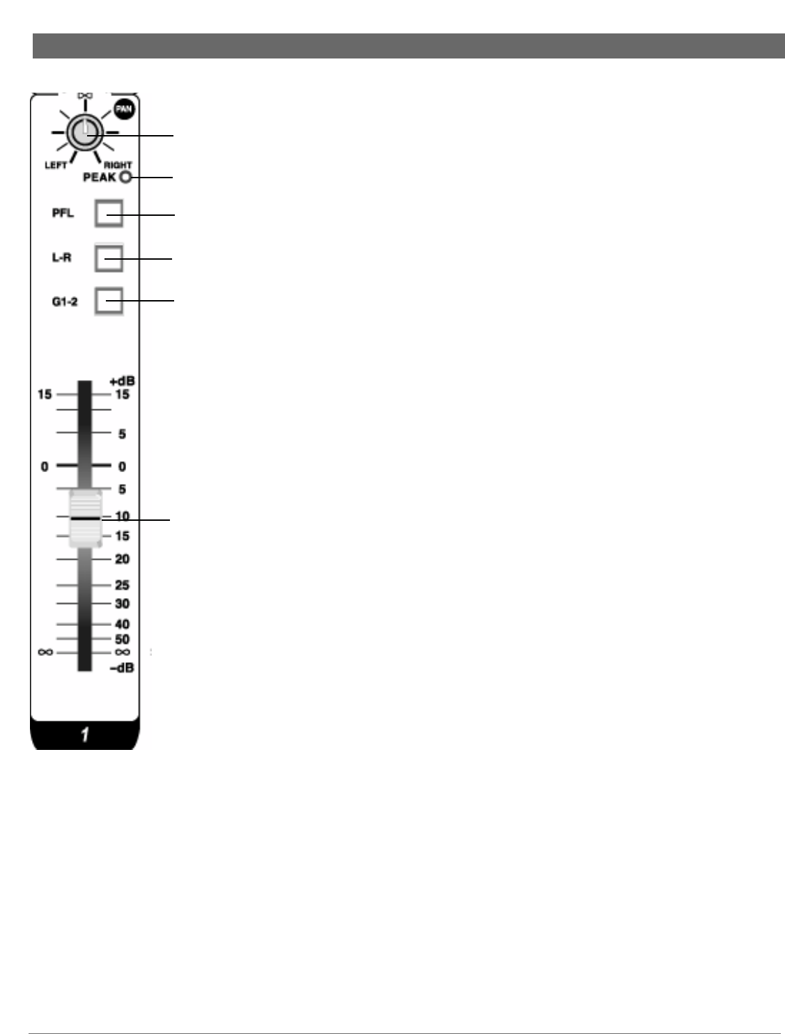
(7) PAN CONTROL
The Channel Pan positions the output of the channel in the
stereo field of the main mix if the L-R Select switch (10) is
depressed. Its constant-power design ensures there are no
level discrepancies whether a signal is hard-panned, center-
stage, or somewhere in-between. Channel Pan also deter-
mines the stereo position of any signal routed to the G1-2
bus, when G1-2 bus is selected with the G1-2 button (11).
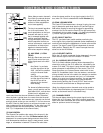
(8) PEAK LED INDICATOR
The Peak LED illuminates when a channel is going into over-
load. It detects the peak level after the EQ and will light at
3dB before clipping to warn that the signal is approaching
overload. You do not want the Peak LED to light except very
intermittently during a take or a mix. If it does light persistent-
ly, reduce input gain with the TRIM control (4).
(9) PFL SELECT SWITCH
The PFL (pre-fader listen) switch enables monitoring the
mono signal of any channel(s) selected (button depressed) at
nominal levels though the headphone or control room monitor
outputs. The signal is post EQ and independent of channel
fader position. Selecting the PFL never interrupts the main
stereo out or the AUX sends.
(10) L-R SELECT SWITCH
When the L-R switch is selected (button depressed), the post
fader channel signal is fed to the master L-R faders.
(11) G1-2 (GROUP) SELECT SWITCH
The G1-2 switch enables selecting (button depressed) the
channel for routing to the G1-2 stereo bus, controlled by the
master G1-2 fader. This signal is post channel fader and the
stereo placement is adjusted by the Pan control. The G1-2
Group bus offers you a second stereo submix with its own
stereo G1-2 submaster fader. It can be used as a convenient
mixing aid both live and in the studio; for example, to combine
the outputs of all drum channels onto just 1 or 2 submaster
faders, or to route to multi-track recorders. You can generate
two mono subgroups in addition to the normal Main Mix
stereo bus by patching the G1 and G2 OUT back into two
mono channels, and use these as Subgroup masters
(Note: the subgroup return channels must not be routed to
the G1-2 bus themselves, by depressing their G1-2 select
switch, as that would result in a feedback loop).
(12) CHANNEL FADER
The channel faders determine the output signal level to the
Master Mix or G1-2 buses. They offer a smooth logarithmic
taper more often associated with much more expensive con-
soles for optimum control of the signal.
(7)
(8)
(9)
(10)
(11)
(12)
7