


5
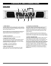
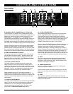
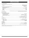
8. BALANCED INPUT CONNECTORS (1/4" TRS & XLR)
These balanced 1/4” (6.3mm) TRS (Tip/Ring/Sleeve) phone
jacks and balanced XLR jacks are designed to accept line level
balanced or unbalanced signals for each channel. They are
wired Tip/Pin 2 = (+), Ring/Pin 3 = (-), and Sleeve/Pin 1 =
Ground. Balanced input signals are recommended, as they are
less prone to AC hum. For long cable runs, a source of less
than 600Ω output impedance is needed to avoid signal loss. For
short cable runs an unbalanced signal input should be suitable.
Since the TRS phone jacks and XLR jacks are wired together
internally for each channel, you can parallel these jacks with
another amplifier by connecting either the 1/4" jack or the XLR
jack to the input jack of another amplifier. You can also parallel
the inputs of two channels together using this same technique.
9. LOW PASS FREQUENCY CONTROL
This control adjusts the roll-off frequency point of the internal
low pass filter from 50Hz to 250Hz. Adjust this control, with
music playing, to find the frequency setting that delivers the
best punch from your subwoofers. The Filter/Source Switch
(10) must set to ON to use this function.
10. FILTER / SOURCE SWITCH
This switch enables or disables the internal low pass filter.
When the switch is set to ON, the internal low pass filter is
enabled, the Subwoofer inputs should remain unused, and the
input signals of channel 1 and 2 are used as the source for the
subwoofer. The Ch 1 and 2 signals are combined and sent
through the crossover and on to the Subwoofer output.
When the switch is set to OFF, the internal crossover is
disabled and the Subwoofer input is used as the source. This
allows the use of an external active crossover or using the Sub
channel to pass full-range signals for monitor feeds or sound
reinforcement.
11. LOW CUT FILTER SWITCH
This switch enables/disables the low cut filter for the Subwoofer
output. The filter has a fixed roll-off frequency at 30Hz with
12dB/octave of cut. This can tighten up the sound while
reducing muddy bass and stage rumble. This filter is only
active when the Filter/Source Switch (10) enabled.
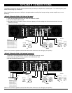
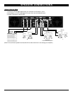
12. OUTPUT CONNECTORS
These binding post (banana) connectors can accommodate
banana plugs, MDP modular dual plugs, or they can be
unscrewed and used for simple binding post connections.
Make sure all connections are tidy and there are no loose wires
sticking out that could short the outputs. Connections are as
depicted on the rear panel and in the following SPEAKER
CONNECTIONS section on page 7 of this manual.
[Caution: Make sure that the speaker, speaker connectors, and
wiring can handle the rated output power to avoid damage.
Speaker power ratings (in RMS) should always exceed
amplifier power ratings. Note that prolonged use at levels in
excess of clipping can possibly drive the amplifier into thermal
runaway and damage the internal amplifier and speaker, so
care must be taken not to overload the amplifier. Never use
less than 4
Ω
total impedance for any channel, as this also can
cause the amplifier to overheat and create thermal runaway.]
13. FANS
The four variable-speed fans adjust speed automatically to
maintain the proper internal operating temperature. Never
block the air vents on the front, back, and side panels of the
amplifier to allow proper ventilation.
14. POWER CONNECTOR
The cord connector is used to connect the 115VAC power
source to your power amplifier.
[Caution: Never remove the center grounding pin as this can
cause a serious safety hazard and will immediately void your
warranty.]
15. FUSE
The fuse holder contains a 3AG fast blow fuse. If this fuse
continuously blows, shut off the unit and have it serviced by the
Nady Service Department.
C O N T R O L S A N D C O N N E C T I O N S
BACK PANEL
(8) (9)
(10)
(11)
(12)
(15)
(14)
(13)(8)