


3. INPUT LEVEL CONTROLS
The amplifier is equipped with separate input level controls for each
channel. Before turning on the M25 for the first time, make sure all
level controls are in their normal full-clockwise position. With the
input levels set to the maximum position, the gain is exactly
conforming to THX Ultra
2
™
standards.
Under some circumstances, other settings may be useful for:
• Level-matching - In systems that incorporate speakers of varying
efficiencies, it may be necessary to reduce the settings of some
controls to achieve proper channel-to-channel balance.
• Extended volume-control range - Many stereo systems have so
much voltage gain that the speakers (or your ears) are over-driven
at any volume-control setting higher than 11 or 12 o’clock position
of the volume control. As a result you can use only the lower half
of the volume control’s range, where adjustments are imprecise
and channel-balance errors tend to be greater. If all input level
controls are reduced, you can turn up your preamplifier’s volume
control, making effective use of most of its range. (Suggestion:
Adjust the input level controls so that your preferred maximum
sound levels occur at about 2 or 3 o’clock on the volume control.)
As an added benefit, this procedure suppresses any noise produced
by the preamp’s high-level circuitry (e.g. any residual hum or hiss
that does not go away when the Volume is turned down).
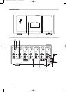
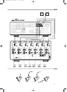
4. SPEAKER CONNECTIONS
This amplifier is equipped with special high-current binding-post
speaker terminals. Connect the loudspeakers with heavy-duty (16-
gauge or thicker) braided wire. Connections may be made in any of
three ways. [See Figure 2.]
• Strip off a half-inch (1 cm) of insulation from each speaker wire. In
each conductor, twist the thin strands of wire together. Unscrew
the knob, insert the bare wire into the opening at the base of the
binding post, and tighten the knob until it grasps the wire securely.
Check to be sure that there are no loose strands of wire touching
the chassis or an adjacent terminal.
• Spade lugs. Unscrew the knob, insert the U-shaped spade lug
behind the bushing, and tighten the knob until the spade lug is
secured.
• Install banana plugs on your speaker wires, and plug them into the
end of each binding post.
NOTE: Speakers must operate in phase with each other in order to
produce a proper stereo image and to reinforce rather than cancel
each other’s output at low frequencies. When connecting speakers,
take care that the red (positive) terminal on each loudspeaker is
connected to the corresponding terminal marked red (positive) on
the amplifier.
5. AUTO TRIGGER ON/OFF
Set the Auto Trigger switch to the ON position to activate the 12V-
trigger. By connecting the 12V-trigger, the M25 can be remotely
switched to On and Standby and vice-versa. When set to the Off
position, the 12V-trigger input is not active.
NOTE: With the Auto Trigger switch set to the ON position and the
12V-trigger input connected, the M25 will switch from Off to
Stand-by when the Power Switch on the front panel is pressed. For
normal operation, ensure the switch is in the OFF position or that
the 12V-trigger input socket is not connected.
6. 12V-TRIGGER INPUT
For external Power on/Stand-by switching, connect the 12V-trigger
output of a source component to this DC input jack. The center pin is
the live or + connection, the outer sleeve of the input jack is the 12V-
trigger - or ground connection.
NOTES: The M25’s 12V-trigger will work within a range of 6 to 15 V
DC level and typically draws less than 10mA of current. Check the
specifications of the 12V-trigger source to ensure it is compatible
with the M25’s 12V-trigger input. Do not exceed the
recommended voltage as this may cause damage to the M25.
7. SOFT CLIPPING
When an amplifier is driven beyond its specified power output it
normally produces “hard clipping” or distortion of the signal. Such
hard clipping, in addition to sounding unpleasant, can damage the
speakers in the system. The NAD Soft Clipping circuit gently limits the
output waveform, minimizing audible distortion and reducing the
change of speaker damage when the amplifier is overdriven. We
recommend that the Soft Clipping switch on the back panel of the
M25 be left in the ON position when system is being operated at levels
that might exceed the amplifier’s power capacity. The LED on the front
panel indicates if Soft Clipping has been engaged.
8. FUSE HOLDER
There is a fuse holder nearby or next to the AC-line cord. In the
unlikely event a fuse may need to be replaced, unplug the line cord
from the wall. Then remove all connections from the amplifier. Only
replace the fuse with the same type, size, and specification.
9. GROUND CONNECTOR
The M25 is provided with a GROUND terminal on the rear panel. This
terminal is connected directly to the chassis of the M25. In the event
of radio hum or radio interference, this terminal can be connected to
a ‘true earth’ such as a copper plated rod driven several feet into the
ground.
8
ENGLISH FRANÇAIS
DEUTSCH
ESPAÑOL
ITALIANO
PORTUGUÊS
SVENSKA
M25 07092005.qxd 1/4/2006 3:35 PM Page 8