


NA
D
4
GB
A NOTE ON INSTALLATION
This unit may be installed on any sturdy, level sur-
face. Since its power transformer generates a mag-
netic hum field of moderate strength, a turntable
(especially one with a moving-coil pickup cartridge)
should not be located near the amplifier.
The amplifier requires ventilation. Do not obstruct
the air outlet grilles on the top or bottom covers, and
do not place the amplifier on a rug or other soft sur-
face. Do not place the amplifier in an enclosed situa-
tion such as in a bookcase or in a cabinet.
SAFETY WARNING: Please ensure that the
Volume controls at the rear of this amplifier are set to
minimum level (i.e. COUNTER CLOCKWISE, viewed
from the back panel).
If this piece of equipment is to be used in a multi-
room ouput of a NAD product, please ensure that
before turning on the system for the first time, the
Volume controls on any auxiliary amplifier ARE SET
TO THE MINIMUM LEVEL.
The multi-room output is not affected by the
Volume or Tone controls (Treble, Bass) of the main
system controls, so care must be taken to prevent
auxiliary amplifiers being driven at full output level.
WARNING TO UK USERS. If this appartus is not
fitted with a UK three-pin plug, do not attempt to
insert the attached plug into a UK mains socket.
Instead, cut the plug from the mains lead and attach
a fused UK three-pin plug using the following safety
advice on wiring.
IMPORTANT. The wires in this mains lead are
coloured BLUE and BROWN;
BLUE: NEUTRAL BROWN: LIVE
The colours of these mains lead wires may not cor-
respond with the coloured markings identifying the
terminals in your plug. In this case the BROWN wire
must be connected to the terminal which is marked
L(ive) or coloured RED. The BLUE wire must be con-
nected to the terminal marked N(eutral) or coloured
BLACK. No connection should be made to the termi-
nal marked E or coloured green or green and yellow
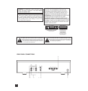
REAR PANEL CONNECTIONS
1. AC LINE CORD
Plug the AC line cord into a nearby wall outlet that
provides the correct AC power line voltage, or into a
switched convenience outlet on your preamp.
2. INPUTS
The 912 has both inputs and outputs. Before mak-
ing connections to the amplifier, make sure the
POWER is switched OFF.
Connect the signal cable from the preamplifier, sur-
round decoder or other signal source to the inputs. If
you want to use the 912 as a single 90-watt amplifier
instead of a stereo 30 W/ch amp, see BRIDGING
(Refer to item 6).
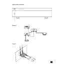
3. LINE OUTPUTS
Each input has an accompanying line output which
will pass the signal on to another amplifier input or
other line-level device. The line outputs are buffered,
so that a low impedance or short circuit placed across
it will not affect the signal at the input. If the 912 is
being used to amplify a remote pair of speakers, con-
nect the system’s preamplifier to the 912’s inputs,
then run a pair of cables from the 912’s outputs to the
inputs of the main stereo amplifier. (See Diagram #1).
4. INPUT LEVEL
The amplifier is equipped with separate input level
controls for each channel. Before turning on the 912
for the first time, make sure all level controls are in
their normal minimum (full-clockwise) power posi-
tion. Under some circumstances, other settings may
be useful for:
(1). Level-matching. In a surround-sound or other
multi-amplifier system, reduce some of the controls
as necessary to balance the system with speakers of
varying sensitivities.
(2). Extended volume-control range. Many stereo
systems have so much voltage gain that the speakers
(or your ears) are over-driven at any volume-control
setting higher than 11 or 12 o’clock. As a result you
are confined to using only the lower half of the vol-
ume control’s range, where adjustments are impre-
cise and where channel-balance errors tend to be
greater. If all input-level controls are reduced, you
can turn up your preamplifier’s volume control, mak-
ing effective use of most of its range. (Suggestion:
adjust the input level controls so that your preferred
maximum sound levels usually occur at about 2 or 3
o’clock on the volume control.)
As an added benefit, this procedure suppresses
any noise produced by the preamp’s high-level cir-
cuitry (e.g. any residual hum or hiss that does not go
away when the Volume is turned down).
(3) Balance correction. Small errors in channel
balance can dramatically degrade the apparent
“depth” and “air” of the stereo image. Such balance
errors may be due to normal production-line differ-
ences in speaker sensitivity, differences in the
acoustic environment around the two speakers, and
slightly different distances from your chair to each
speaker. You can use the input-level controls to cor-
rect these fixed balance errors, freeing your preampli-
fier’s balance control to correct balance errors in
recordings.
Switch the preamp to mono and sit in your normal
listening location. Ideally the “phantom” central
image should seem to be floating in mid-air midway
between the left and right speakers. If it is located
off-center, closer to one speaker, turn down the input-
level control for that channel slightly in order to re-
center the phantom mono image. Then restore the
preamp to normal stereo operation.
5. SPEAKER CONNECTIONS
This amplifier is equipped with special high-current
binding-post speaker terminals to handle the highest
peak power levels that may occur in the “bridged”
NAD 912 POWER AMPLIFIER