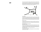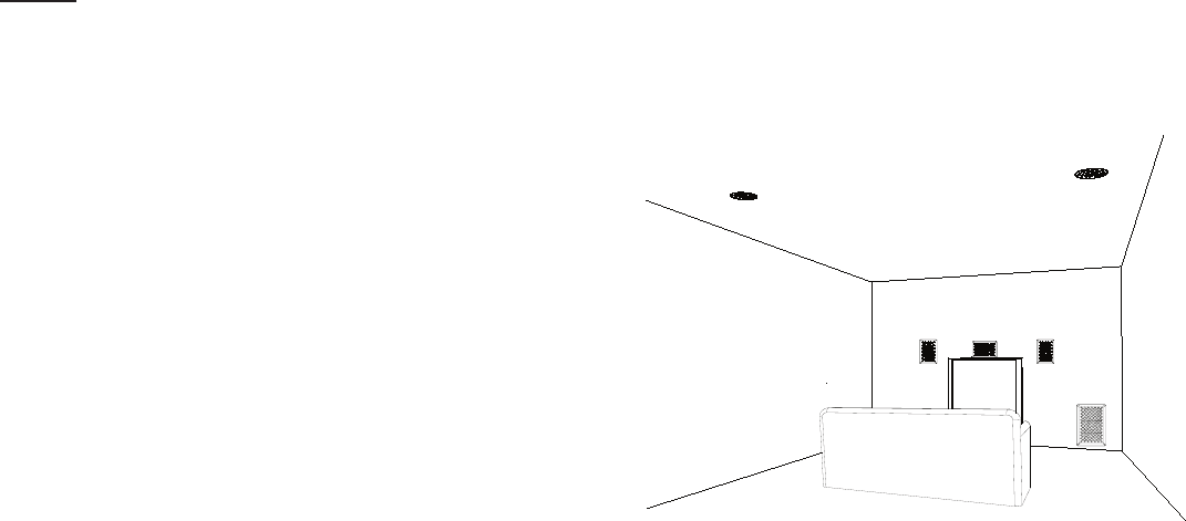
Figure 3 shows an example of speaker placement in the listening room when using a complete set of MU-
SICA In-Wall and In-Ceiling models in a home theater system. In this example, in-wall models are used for
the Front Left and Right channels, and the M2525LCR in-wall center is used for the center channel. The
M800SW in-wall subwoofer is used for the LFE channel, and in-ceiling models are used for the Left and
Right Rear surround channels. The M2525LCR should be placed as near to the television monitor as pos
-
sible. It is video shielded to prevent picture distortion on the monitor. If possible, the M800SW subwoofer
should be placed near to a corner boundary to maximize the low frequency response. The surround
speakers should be placed to the side of the listening position and slightly behind it.
Model M800SW..
This model is a subwoofer designed to augment the bass response of a system. It should be used with
full range speakers that need additional low frequency output. It can reproduce the Low Frequency Effects
(LFE) channel in a home theater system. This model does not include any lowpass filtering itself. That
means the user must use external lowpass filtering to properly integrate the subwoofer with the rest of the
audio system. When M800SW is connected to the LFE channel of a home theater system, the audio/video
receiver or processor will provide the necessary lowpass filtering. If this model is used in a two channel
stereo music system, the user must be sure that the signal to the M800SW is lowpass crossed over below
150Hz.
Stereo Input Models..
Models M622C and M822C are designed for use in small rooms such as bathrooms or hallways or any-
where that both channels of a stereo signal need to be reproduced while taking up a minimum amount of
ceiling space. Both models utilize a dual voice coil woofer design that allows both channels of a stereo
system to drive one cone. This feature, coupled with a dual tweeter system, allows these models to oper
-
ate as two speakers in one.
Wall and Ceiling Thickness Considerations..
Maximum Material Thickness
All of the MUSICA In-Wall and In-Ceiling speaker models included in this booklet will mount to walls and
ceilings up to 1” thick with the mounting wings in the normal position supplied from the factory. If the thick
-
ness of the wall for ceiling is greater than 1”, the mounting wings must be turned upside down in the tracks
to accommodate the thicker material. Reversing the direction of the wings will allow the speaker to be
installed in walls and ceilings up to and including 1 1/2” thick. To reverse the direction of the wings, reverse
the mounting screws all the way out of the wings. Then carefully pry the wings out of the tracks. Turn the
wings over, place them back in the tracks, and reinstall the mounting screws.
Minimum Material Thickness..
The following models can be installed in wall and ceiling material all the way down to 0” thick: M2525LCR,
M512W, M612W, M625W and M800SW.
The following models can installed in wall and ceiling material down to 1/8” minimum: M512C, M612C,
M622C, M625C, M812C and M822C.
Figure 3
NOTES


