


6
3
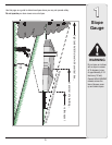
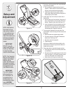
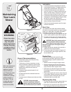
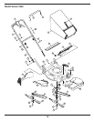
Setup and
Adjustment
1. Remove any packing material which may be between
upper and lower handles.
a. Pull up and back on upper handle as shown in
Figure 3-1. Make certain the lower handle is seated
securely into the handle mounting brackets.
b. Tighten star knobs securing upper handle to
lower handle. Make sure that each carriage bolt is
seated properly in the handle.
2. Locate hairpin clip on the weld pin on each side of
lower handle.
a. Remove hairpin clip from this hole. Using a pair of
pliers, insert hairpin clip into the other hole on the
weld pin. Repeat on other side. See Figure 3-2.
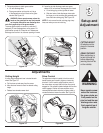
b. Insert a carriage bolt from the hardware pack into
the upper hole on the handle mounting bracket.
Secure with one plastic wing nut, also included in
the hardware pack. Repeat on other side.
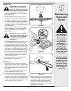
3. The rope guide is attached to the right side of the
upper handle. Loosen the wing nut which secures the
rope guide.
a. Hold the blade control against upper handle.
b. Pull starter rope out of the engine. Release the
blade control. See Figure 3-3.
c. Slip starter rope into rope guide.
d. Tighten wing nut.
Insert post on cable ties into holes provided on the
lower handle. Pull cable tie tight around cables and
handle and trim excess.
4. Follow steps below to assemble the grass catcher:
a. Place bag over frame so that its black plastic side
is at the bottom.
b. Slip plastic channel of grass bag over hooks on the
frame. See Figure 3-4. All plastic channels except
center top of bag attach from outside of bag.
c. Attach center top of bag from inside of bag.
Figure 3-3
Figure 3-2
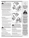
NOTE: Stand behind
the mower as if you
were going to operate
it. Your right hand cor
-
responds to the right
side of the mower; your
left hand corresponds
to the left side of the
mower.
Figure 3-1
IMPORTANT
This unit is shipped
without gasoline or
oil in the engine. Fill
up gasoline and oil
as instructed in the
accompanying engine
manual BEFORE
operating your mower.
Figure 3-4
IMPORTANT
DO NOT crimp the
cables when lifting the
handle up. Make sure
to route the cables
under the lower handle.
C
B
A
A
B
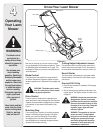
NOTE: This Operator’s
Manual covers several
models. Lawn Mower
features vary by
model. Not all features
discussed (or engines
pictured) in this manual
are applicable to all
Lawn Mower models.
A
B
A
C
D
B