


SATELLITE CONTROL STATIONS
NWRC14 SERIES
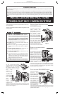
At each satellite control
station location, strip
approximately 4 Inches of
jacket (MS4XSC and
MS2SXSC) from wires and
separate colored
conductors from one
another. Strip 1/2 Inch of
insulation from each
conductor. Connect drain
wires together from both
cables using a wire nut
(MS4XSC only). Connect
each colored conductor
together using wire nuts as shown in fi gure 7. Terminate Blue and
Violet wires to the corresponding terminals of the satellite speaker(s).
Mount satellite control station to mounting ring or housing using the
two screws provided with the station.
EXTERNAL MUSIC SOURCE AWPM
Connect the cable from the
gang box to one of the 'Y'
cables shipped with the
AWPM wall plate as shown in
figure 8. Use the labels
provided to mark the two jacks
used and the two that are not
used. Connect one of the 'Y'
cables to the plate as shown
and mount the plate using the
two screws provided.
DOOR STATIONS SERIES DS3/DS3B
& BD3/D3/BD3B/D3B
At each door station
location, strip approximately
4 inches of jacket from wire
and separate colored
conductors from one
another. Strip 1/2 inch of
insulation from each
conductor as shown in fi gure
9. Cut each shield drain wire
at jacket to prevent them
from touching each other
(MS4DCXSC only).
Terminate yellow and
orange wires to the screw terminals on the bell button (if equipped).
Connect the Red and Black wires to the Red and Black wires on the
speaker respectively. Refer to fi gure 9. Mount door station to housing
using the two screws provided with station.
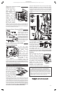
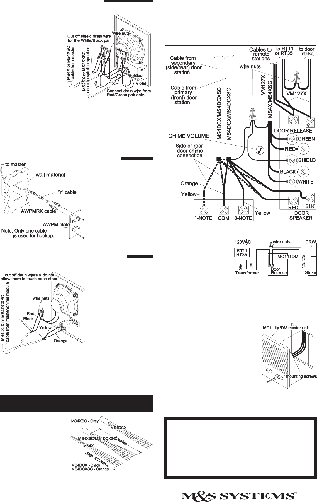
Gather all remote and door
station cables and cut cable
ends to the same length
approximately 12 Inches from
entry point in wall housing.
Strip off approximately 8
Inches of jacket and shield foil
from each cable (MS4XSC/
MS4DCXSC). Strip 1/2 Inch
of insulation from each
individual conductor. See fi gure 10. Be careful not to damage wall
surface. Pigtail all shield drain wires (bare) to the shield terminal on the
master. Insulate the bare wires using some of the jacket material to
prevent shorting the circuit board. Group all Red, Black, White and
Green wires from the remote stations (MS4X/MS4XSC cables) and
connect to the Red, Black, White and Green terminals respectively
on the master unit as shown in fi gure 11. Do not connect the
door stations at this time (MS4DCX/ MS4DCXSC).
Figure 7
Fi
g
ure 8
Figure 9
MC111M/DM series master station hookup
Figure 10
Connect the Red and Black wires of the door station cable(s)
(MS4DCX/ MS4DCXSC) to the Red and Black door speaker
terminals of the master as shown in fi gure 11. Connect all Orange
wires from the Door stations to the Common terminal labeled
COMMON. Connect each Yellow wire to each note selection
terminal. (Do not connect more than one Yellow wire per note
terminal.)
For implementation of the
DRW door release, connect
the VM127X cables from the
remote power transformer
and the DRW door release
striker as shown in fi gure 12.
The 24Volt/1 Amp dry
contact switch closure may also be used for home automation or
security panel panic alarm interface. Note: The door release
operation may only be used for one type of function per
application.
After all connections have been made,
insert the power plug into the
transformer connector. Secure the
master to the wall housing using the 2
screws provided. Do not overtighten
the screws as the plastic may distort or
crack. Check all functions by following
the guidelines in the operating guide
shipped with the master unit. If any
diffi culties are encountered, recheck all
connections. If, after reviewing these
instructions, you are unable to resolve
any problems, contact technical support at 1-800-366-9422.
Figure 11
Figure 12
Figure 13
M&S SYSTEMS 2-YEAR "NO FAULT" LIMITED WARRANTY
M&S Systems warrants for two years from the date of “fi rst user” purchase all MC111 products to be free
of factory-caused defects in material and workmanship. M&S Systems will repair or replace. at its option,
parts and materials at no charge, regardless of the problem. This warranty extends to the original purchaser
of the product and to each subsequent owner of the product during the term of this warranty. This NO FAULT
warranty covers only the liability described above, and does not include liability for incidental or
consequential damages. NOTE: Some states do not allow the exclusion or limitation of incidental or
consequential damages, so the above limitation or exclusion may not apply to you.
115739 B
PRINTER’S INSTRUCTIONS:
INSTR,INSTL,FINISH-OUT,MC111M - LINEAR P/N: 115739 B - INK: BLACK - MATERIAL: 20 LB. MEAD BOND - SIZE: 8.500” X 14.000” - SCALE: 1-1 - SIDE 2 OF 2