


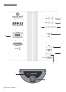

1. RCA Line Level Inputs (Stereo Left & Right)
For connection to a 2 channel/ stereo amplifier system. Connection should be provided by a pair of high-quality signal
cables from the pre-out section of an amplifier. Note: - cable lengths should not exceed 10 metres to avoid interference
from other electrical appliances.
2. RCA Line Level Outputs (Stereo Left & Right)
RCA line level outputs are provided in order to use other sub-woofers in conjunction with the GSW12 by ‘daisy chain’ type
connection. The outputs are link out only connections and do not provide any form of filtering.
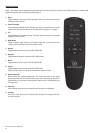
3. LFE Input (RCA Type)
This input is to be used when connecting the GSW12 to an AV amplifier/receiver. When using the LFE input, the crossover
function in the menu/set-up is not used. This is due to the crossover function being controlled by the AV amplifier/
processor to which it is connected. Please refer to the crossover table on page 10 for further advice on which setting to
use. Input between LFE and Stereo input (Inp) can be switched using the ‘LFE’ button on the remote control unit.
4. LFE Output/Link (RCA Type)
LFE output is provided in order to use other sub-woofers by ‘daisy chain’ type connection. The output is a link out only
connection and does not provide any form of filtering.
5. 12 Volt Trigger Input ~ Centre Pin = +12Vdc.
For external power control from AV amplifier/Receiver to the GSW12. Monitor Audio recommend using this function and a
lead is supplied. This 12 volt signal is supplied by the AV amp/receiver and tells the GSW12 to turn on from standby mode.
This allows a more accurately controlled method of the auto on/off function. It is also a lot more energy efficient. The
display will change from a clock to a ‘3.5mm jack’ image (see key on page 1 of Set Up Guide for illustrations). The stand by
function on the remote will not be operable when using the +12v trigger.
6. Mains Power Switch
Mains ‘rocker switch’ providing overall power off and on/auto. In the on/auto mode, the unit will turn on when an input
signal is sensed, and will turn off after a user preset delay when the signal is removed (source turned off).
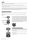
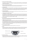
7. IEC Mains Power Connector/Fuse Location
The GSW12 is supplied with a two-pin mains input socket for connection to the mains supply. Use ONLY the appropriate
IEC mains lead provided with the product. Also fitted is an external mains fuse. If a fuse blows during operation a spare
fuse is provided within the fuse holder for replacement. If you wish to change the fuse, you can do this by removing the
IEC mains lead and carefully levering out the original fuse from its holder below the IEC mains input socket (7a). If the fuse
blows again it is advisable to seek help from an authorised service agent. DO NOT attempt to re-fit a further fuse as this
could result in serious damage to the amplifier unit.
8. Recycling and Approval Certication
The approval identities will differ to that displayed depending on the country you are in.
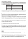
9. Display
This LCD display provides full feedback of the amplifier settings. The default display will show the EQ settings, the
output volume and graphic output display (constantly changing). When the enter button is pressed (on the remote), or the
encoder pushed down, the ‘menu’ system is displayed. For full details of the menu system, please go to page 9.
10. Push-Turn Control Button
This gives you full control (except EQ selection) of your GSW12. By default, you can adjust the volume (by
turning the control button) and enter the menu system. Pushing the rotary encoder allows access of the menu system
illustrated on page 9. For more detailed operation and set up please refer to page 10.
Output Level
Graphic Output Display
EQ Setting (e.g. Impact)
Input (e.g. Stereo Input/LFE)
monitoraudio.co.uk
7