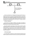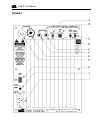
A) Input Gain Switch - Fixed is equal to maximum input gain on the variable gain
knob. 200mv delivered to the balanced input stage delivers 90dB of acoustic
output at one meter.
B) Variable Input Gain Switch - Offers variable gain from -∞ to maximum gain,
which is equal to having the gain switch set to the reference position.
Reference denotes the position that should be used when operating this monitor
with +4dBu input signal.
C) Narrow/Wide Switch - See section 6 - Narrow/Wide Mode
D) 80 Hz High-Pass Filter In / Out - When this switch is in the IN position, an
12dB per octave 80 Hz High-Pass Filter is placed in line on the input stage of
the monitor. This switch should be in the OUT position when used with any
bass-management controller, such as an LFE-3, 4 or 5, or any other [consumer]
processor that has internal 80 Hz High-Pass filters.
E) Unbalanced Input - this RCA type input terminal is connected in series with the
Unbalanced Output.
F) Unbalanced Output - this RCA type output terminal is connected in series with
the Unbalanced Input.
G) Neutrik Balanced Input - this input terminal is connected in series with the
Balanced Output and features both XLR and Phone connections. Pin 2 is hot.
H) Neutrik Balanced Output - this output terminal is connected in series with the
Balanced Input and uses a standard XLR connection. Pin 2 is hot.
I) Standard IEC Power Cord Receptacle
J) Fuse holder - 5 Amp Slow-blow type fuse
K) Power Switch
14. Inputs & Controls
(see Figure 5)
S-150P THX Manual


