


MAXON
SP-300 HAND HELD
Page -8-
May 2001
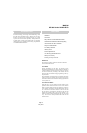
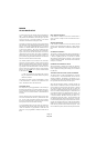
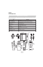
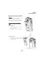
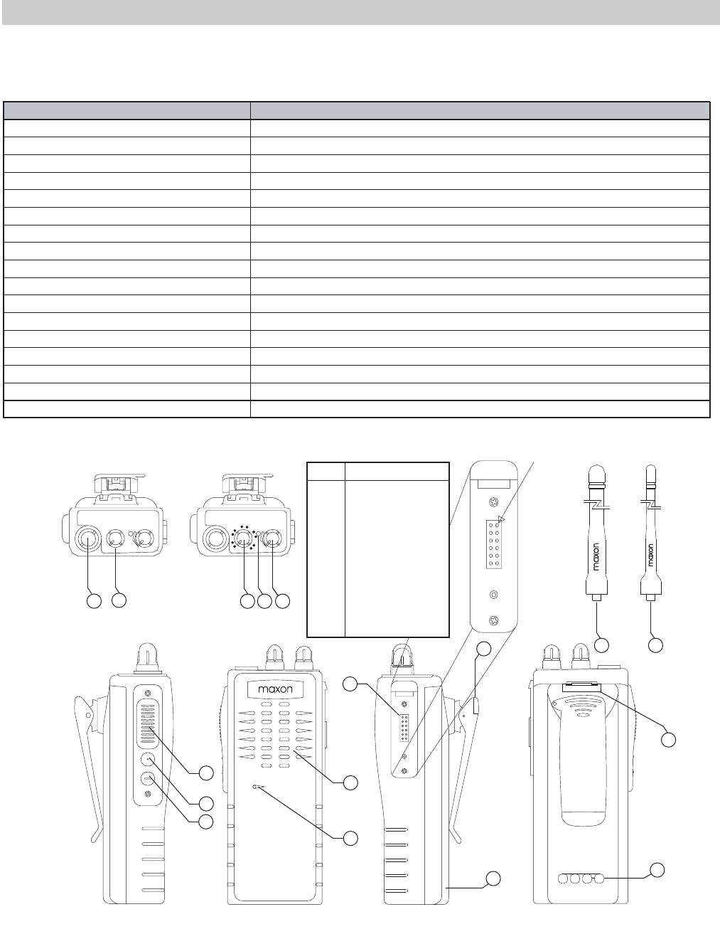
The controls, indicators and antenna connections on the VHF and UHF Scanning Handheld Series radios are all located on the
top panel. The accessories socket is located on the radio chassis right hand side. The monitor and PTT buttons are located on
the radio chassis left hand side.
DESCRIPTION OF CONTROLS
ITEM DESCRIPTION
1. Antenna Connector 1/4" UNEF socket
2. 4 Channel Select Switch Rotary switch, used to select one of four and to engage in scanning function
3. 16 Channel Select Switch Rotary switch, used to select one of sixteen and to engage in scanning function
4. Status Indicator (busy TX/BT) Tri-colored LED indicator
5. ON/OFF Volume Control Main power switch and volume control. Fully counter-clockwise is OFF position
6. Battery Lock Used to lock the battery in place
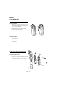
7. Push-To-Talk Button Push to talk, release to listen
8. Monitor Button When pressed, monitors the chosen channel
Used for controlling installed external option
9. Option
10. Speaker Sound reception
11. Microphone Sound transmission
12. External Speaker Socket used for external microphone with speaker
13. Belt Clip
Belt Clip
14. Battery
Power Supply
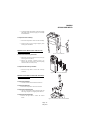
15. Battery Charger Contacts
Contacts used for charging battery
16. VHF Antenna
Antenna
17. UHF Antenna
Antenna
1
9
8
7
10
12
13
14
15
11
2
3 4 5
6
16 17
ANT CH
VOL
1
4
7
11
13
16
ANT CH
VOL
4
3
2
1
maxon
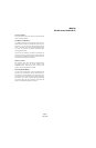
CON701 - Pin 1
1
2
3
4
5
6
7
8
9
10
11
12
Data
Clock
N/C
+7.5V
N/C
N/C
Gnd
Mic+
N/C
Int_Spkr_Mic_Dsbl
Spkr+
N/C
Pin Function
CON701 Pinouts