


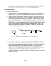
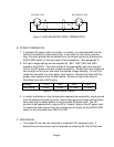
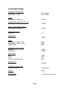

PREAMP END
1
3
2
1
3
2
301
RECORDER END
Figure 2. 600Ω BALANCED CABLE TERMINATION
B. POWER TERMINATION
1. A standard AC power cable is included. For safety, it is recommended that the
cord be connected to a grounded outlet. In the event of noise from a ground
loop, the audio ground can be isolated from the chassis ground by throwing the
AUDIO GND switch on the rear panel of the preamplifier. (See paragraph 3)
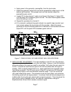
2. AC input voltage settings can be adjusted for 100V, 120V, 220V and 240V
operation at 50-60Hz. From the outside of the preamplifier, open the trap door
next to the IEC power inlet with a small screwdriver. Carefully pull the voltage set
cam straight out and then insert with the desired voltage showing. Do not try to
rotate the cam while it is in the power input module. Replace the fuses with the
proper value selected from the table below. Be sure to use a time delay or
Slow-Blow fuse with a 250V rating
Voltage 100V 120V 220V 240V
Fuse rating 0.25A 0.25A 0.125A 0.125A
Figure 3. FUSE VALUE TABLE
3. In certain installations it may be desirable separate the preamplifier signal ground
from the chassis and earth grounds. Noise inducing ground loops can be broken
while retaining the safety feature of the grounded AC power cord. The 201
should not be operated with a ground lift or "cheater" plug on the AC power cord.
To isolate the audio ground from the chassis ground simply set the AUDIO GND
switch on the rear panel from EARTH to ISO.
C. MECHANICAL
1. The model 201 can be rack mounted in a standard 19" equipment rack. If
desired the rack mount ears can be removed by removing the 3 #6-32 flat head
Page 5