


Acoustical
1
(each loudspeaker)
Coverage
Crossover
Transducers
Standard Audio
Input Module
Amplifiers
AC Power
Physical
Notes
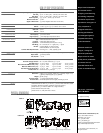
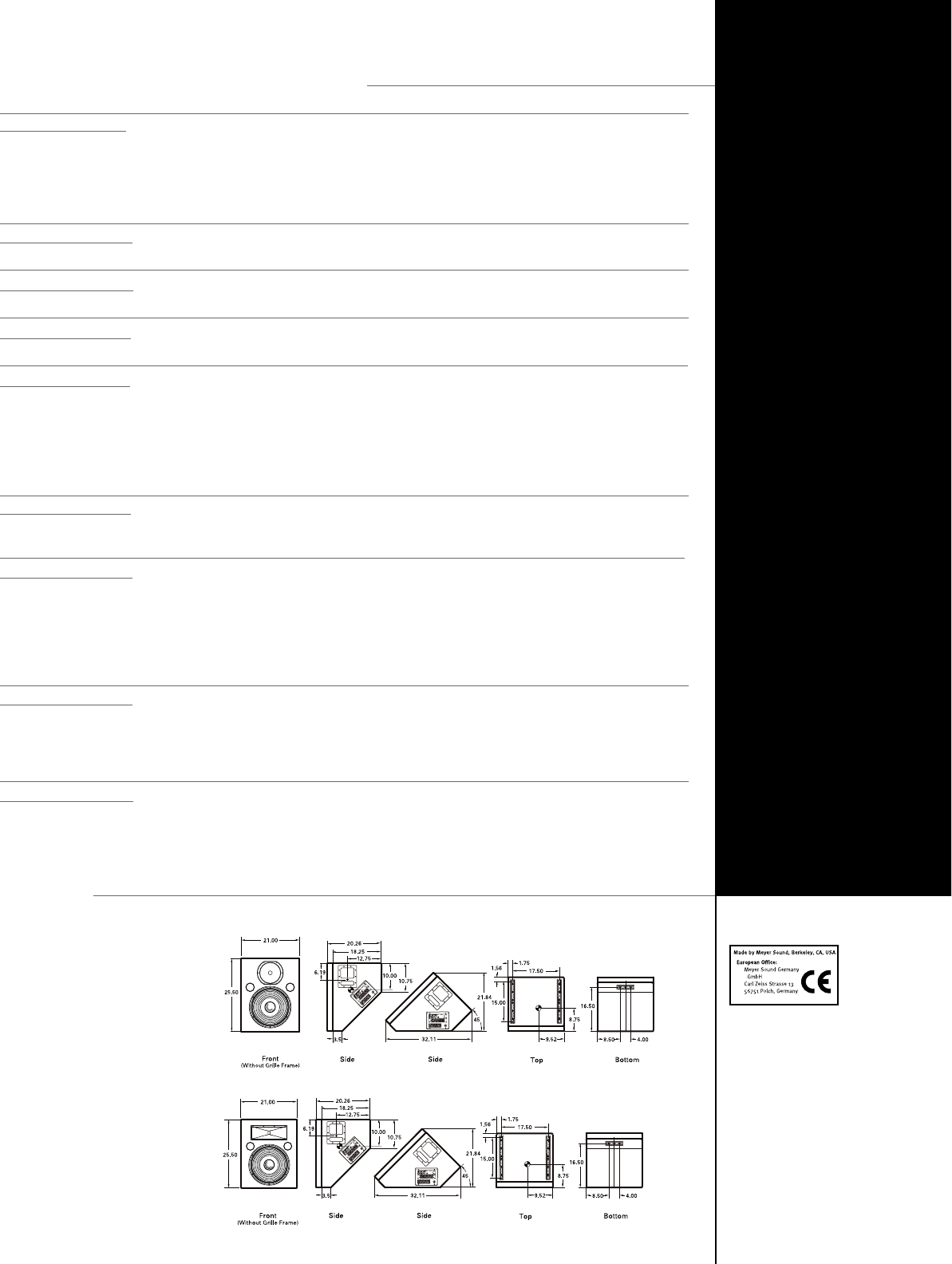
PHYSICAL DIMENSIONS
USM-1P/100P SPECIFICATIONS
Operating Frequency Range
2
Free Field
Half-Space
3
Phase Response
4
Maximum Peak SPL
5
Signal to Noise Ratio
USM-100P
USM-1P
USM-100P
USM-1P
Low Frequency
High Frequency
Type
Connector
Impedance
XLR Wiring
RF Filter
Common Mode Rejection Ratio
Type
Output Power
THD, IM, TIM
Connector
Automatic voltage selection
Idle RMS Current
Max Continuous RMS Current (>10 s)
Max Burst RMS Current (<1 s)
Max Peak Current During Burst
Soft Start Turn-on
Dimensions
Weight
Enclosure/Finish
Protective Grill
30 Hz – 20 kHz
44 Hz – 16 kHz ±3 dB; –6 dB at 40 Hz and 20 kHz
40 Hz – 16 kHz ±3 dB; –6 dB at 33 Hz and 20 kHz
±35° 500 Hz – 16 kHz; +90° at 120 Hz
132 dB
>95 dB (A-weighted noise floor to max SPL)
–6 db at 100° H x 40° V; -10 dB at 120° H x 60° V
–6 db at 45° H x 45° V; -10 dB at 60° H x 60° V
900 Hz
1000 Hz
15-inch cone driver
3-inch diaphragm compression driver
Differential balanced input circuit
Female XLR; Male XLR Loop
10 kΩ differential (between pins 2 and 3)
Pin 1: chassis; Pin 2: + signal; Pin 3: – signal
Common Mode: 425 kHz low-pass;
Differential Mode: 142 kHz low-pass
>80 dB (50 Hz – 1 kHz); typically 90 dB
Complementary power MOSFET output stages, class AB/bridged
350 Wrms/channel
< .02 %
PowerCon locking AC connector
88 – 264 VAC continuous; 47 – 63 Hz
115 V: 0.25 Arms 230 V: 0.13 Arms 100 V: 0.3 Arms
115 V: 2.8 Arms 230 V: 1.4 Arms 100 V: 3.2 Arms
115 V: 3.2 Arms 230 V: 1.6 Arms 100 V: 3.7 Arms
115 V: 5.0 Apk 230 V: 2.5 Apk 100 V: 5.8 Apk
Inrush current <15 A @115 V
Height: 16.9” (429mm) ; Width: 16.5” (419mm); Length: 22.4”
(569mm); Depth (w/grill) 15.19” (386mm)
88 lbs (40 kg)
5
/
8
” birch plywood/black textured
Removable perforated steel grill, charcoal grey foam
1. Measurements are taken at 3 m on-axis,
1
/3 octave, unless otherwise stated.
2. Response depends on loading conditions and room acoustics.
3. Measured at 1.5 m with the USM-1P on a single boundary.
4. Phase variation from pure delay.
5. Measured at 1 m, with pink noise or music.
ALL UNITS IN INCHES
Meyer Sound Laboratories, Inc.
2832 San Pablo Avenue
Berkeley, CA 94702
tel: 510.486.1166
fax: 510.486.8356
e-mail: techsupport@meyersound.com
http: www.meyersound.com
Meyer Sound Laboratories
has devoted itself to
designing, manufacturing,
and refining components
that deliver superb sonic
reproduction. Every part of
every component is
designed and built to
exacting specifications
and undergoes rigorous,
comprehensive testing
in the laboratories.
Research remains an
integral, driving force
behind all production.
Meyer strives for sound
quality that is predictable
and neutral over an
extended lifetime and
across an extended range.
© 2000 Meyer Sound Laboratories, Inc.
All rights reserved
Specifications subject to change without notice
UL Approval Pending
USM-100P
USM-1P
USM-1P/100P - 04.089.005.01A
preliminary