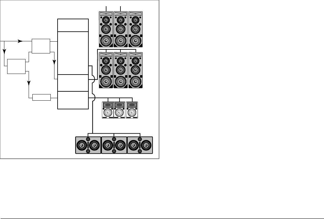
LD-1A WITH FLOWN MTS-4A AND CQ; 650-P ON THE
FLOOR
This example shows the LD-1A integrating a complete system
of self-powered speakers for a large venue. Although channels
1, 3, and 5 constitute half of the system, channels 2, 4, and
6 can be used with identical connections to create the other
half. The upper and lower MTS-4A arrays and CQ down-fills are
flown; the 650-P subwoofers are on the floor.
Set the MTS-4A and CQ to the same polarity. The polarity
for the 650-P depends on the distance of the measurement
position from the flown and subwoofer systems.
The CH 1 Mid-Hi and CH 3 outputs drive the upper and lower
MTS-4A arrays, respectively, applying appropriate levels for
speakers directed at different distances. CH 3 is delayed to
phase align the upper and lower systems in the intersecting
coverage area.
Since the MTS-4A arrays are driven by full-range signals, the
Lo Cut switches for the CH 1 Mid-Hi and CH 3 outputs should
be out. The Array EQ switches should also be out because the
Array EQ filter is designed for the MSL-4, not the MTS-4A.
Since the DS-P Series is not included in this system, the DS-2
& Sub Crossover switch should be out.
CH 5 controls the CQ down-fill system. Since the main system
is more powerful than the down-fill system to project farther
into the venue, the main system is audible in the down-fill’s
coverage area. To insure that the systems combine properly
in this area:
• Set the CQ to the opposite polarity to the MTS-4A to phase
align the mid-hi frequencies and minimize the MTS-4A’s low
frequency down-lobe.
• Use the CH 5 Lo Cut filter to eliminate the low frequency
rise caused by the overlap with the 650-P/MTS-4A systems.
• Delay the down-fill to align with the MTS-4A system in
their intersecting coverage area.
The polarity of the 650-P depends on the height and
distance of the measurement position from the flown and
subwoofer systems. The entire system should be measured,
phase-aligned, and equalized using the SIM System II Sound
Analyzer and CP-10 Parametric Equalizer.
650-P Subwoofers
CQ Down-fills
MTS-4A Lower System
MTS-4A Upper System
Input Mid-Hi
Output
Sub
Output
Input Output
LD-1A
Delay
CP-10 EQ
CH 1
CH 3
Input Output
CH 5
CP-10 EQ
Ch A
A
B
Ch B
The LD-1A with MTS-4As, CQs, and 650-P Subwoofers
DRIVER TROUBLESHOOTING
TROUBLESHOOTING WITH TPL
The TPL LED can indicate serious driver problems, if
interpreted correctly. If one MTS-4A in a system exhibits
substantially more TPL activity than others receiving the same
audio signal, then one or both drivers in that unit may have a
short circuit. This is a potentially dangerous condition for the
electronics; shut the MTS-4A down immediately.
The TPL circuit does not activate if there is no power
dissipation in the driver, regardless of the input signal level.
Therefore, if all MTS-4As in a system receiving the same audio
signal exhibit TPL activity except one, then that unit may
have an open voice coil; disconnect it and contact Meyer
Sound for repair information.
NOTE: The Remote Monitoring System (RMS) provides precise
information about peak power, peak voltage, and
average voltage (VU) for each amplifier channel,
enabling a more complete driver diagnostic than the
TPL LEDs. Contact Meyer Sound for more information
about RMS.
DRIVER REPLACEMENT
To determine whether the high or low drivers are functioning
properly, or replace a damaged driver, contact Meyer Sound to
obtain The Low Driver Inspection and Evaluation Procedure
for Self-Powered Series Products (part # 17.010.120.01) or
The High Driver Inspection and Evaluation Procedure for
Self-Powered Series Products (part # 17.010.120.02).
VERIFYING DRIVER POLARITY
Incorrect driver polarity impairs system performance and may
damage the drivers. All Meyer loudspeakers are shipped with
the drivers in correct alignment. However, if the driver or
circuit wiring has been removed or disassembled in any
loudspeaker in a system for any reason, it is essential to check
the polarity between drivers in the same cabinet and between
adjacent loudspeakers.
9
