15
CHAPTER 3: THE MM-4XP LOUDSPEAKER
THE MM-4XP CONNECTOR
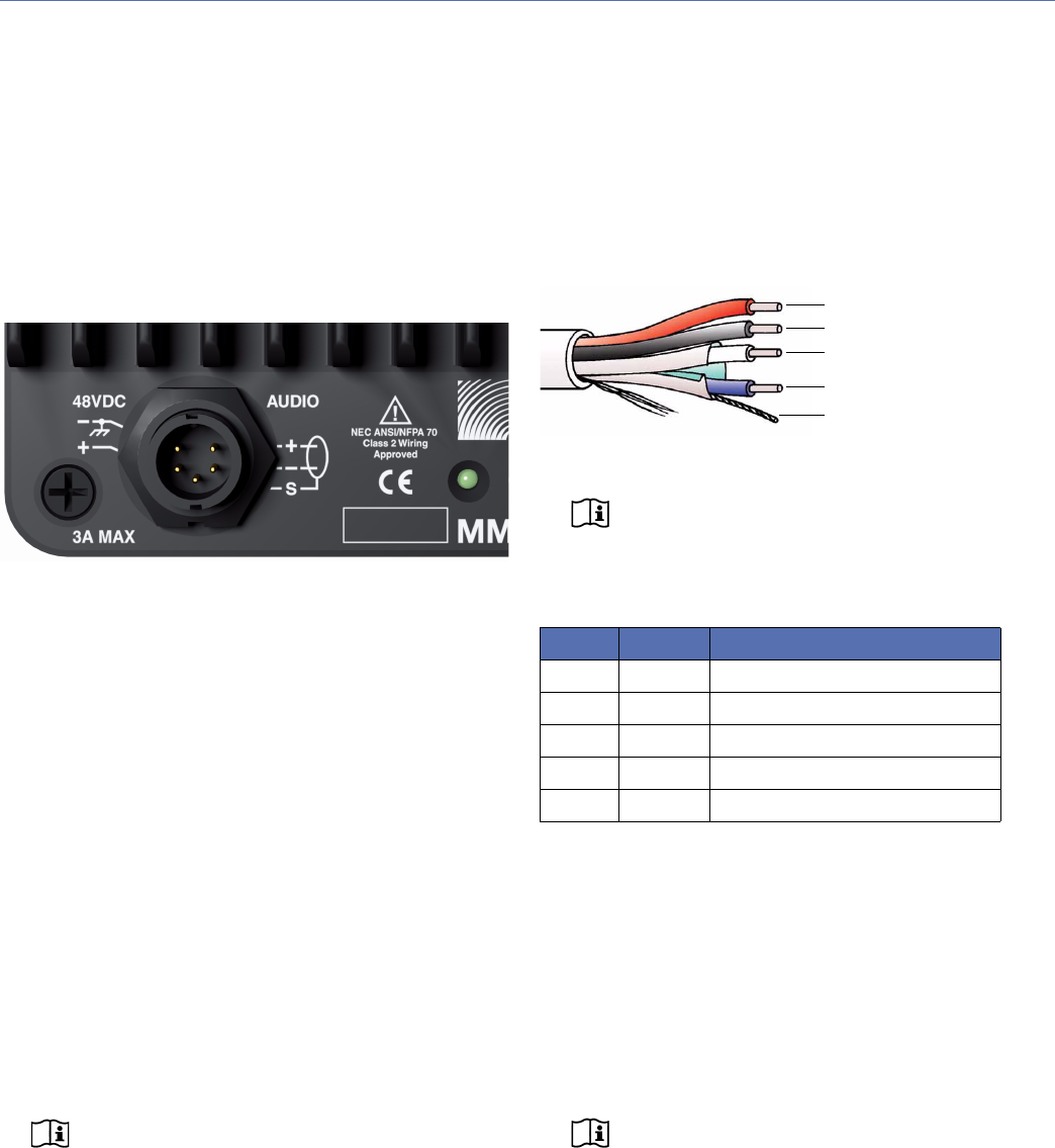
The MM-4XP receives DC power and balanced audio from a
EN3 5-pin male connector on its rear panel. The connector’s
five pins include two for DC power (negative and positive)
and three for balanced audio (shield, negative, and positive).
To function properly, the MM-4XP requires 48 V of DC
power.
A single composite cable (such as Belden 1502) wired for
both DC power and balanced audio can be used to connect
the MM-4XP to one of the MPS-488’s eight Channel Out-
puts.
Wiring the EN3-to-Pigtail Cables
Each MM-4XP loudspeaker comes with one EN3 5-pin
female to pigtail cable. The EN3 end of the cable connects
directly to the MM-4XP connector. The pigtail end of the
cable can be equipped with either an EN3 5-pin male con-
nector for connecting to the MPS-488
E power supply, or a
Phoenix 5-pin female connector for connecting to the
MPS-488
E power supply. The pigtail can also be spliced to a
longer loudspeaker cable or to a junction box. The included
EN3-to-pigtail cable uses Belden 1502 cable, which can be
wired for both DC power and balanced audio. The EN3-to-
pigtail cable is available in plenum or regular (non-plenum)
versions.
NOTE: For a complete list of cables and cable
connectors available from Meyer Sound that
can be used with the MM-4XP loudspeaker and
MPS-488 power supply, see Appendix B, “MM-4XP
Accessories.”
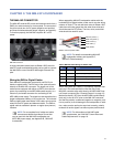
When assembling MM-4XP loudspeaker cables with the
included EN3-to-pigtail cables, make sure to use the wiring
scheme in Table 2. The red and black wires in Belden 1502
cable have a thicker gauge than the other three wires and
should be used for DC power. The blue, white, and shield
wires should be used for audio.
NOTE: For details on assembling MM-4XP
loudspeaker cables, see Appendix C,
“MM-4XP Cable Assembly.”
When wiring MM-4XP cables, it is extremely important that
each pin in the cable be wired so that the pins in the
MM-4XP connector align with those in the MPS-488 Chan-
nel Output connector (see “Channel Outputs” on page 12).
Make sure the 48 V DC from the MPS-488 is wired directly
(and only) to the 48 V DC pins on the MM-4XP connector,
and that the polarity is observed (negative to negative, posi-
tive to positive) to avoid damage to the loudspeaker. In addi-
tion, make sure the audio pins are wired correctly; polarity
reversals for audio signals can affect system performance.
NOTE: For information on MM-4XP cable
requirements, see “MM-4XP Current Draw and
Cable Requirements” on page 16.
MM-4XP Connector
Belden 1502 Composite Cable
Table 2: MM-4XP Cable Wiring for Belden 1502
Wire Gauge Signal
Red 18 AWG DC power, positive (+)
Black 18 AWG DC power, negative (–)
White 22 AWG Balanced audio, positive (+)
Blue 22 AWG Balanced audio, negative (–)
Shield 24 AWG Balanced audio, shield
Red: DC power (+)
Black: DC power (–)
White: audio (+)
Blue: audio (–)
Audio shield


