12
•
M3D
™
Line Array Meyer Sound Laboratories Inc
With these two technologies (low-frequency line array
and high-frequency wave guide) combined in a single
product, it's important to understand how to best
electronically drive a hybrid line array. The high-
frequency section can, and usually should, be zoned for
implementing different equalization into zones. The first
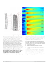
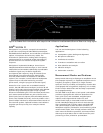
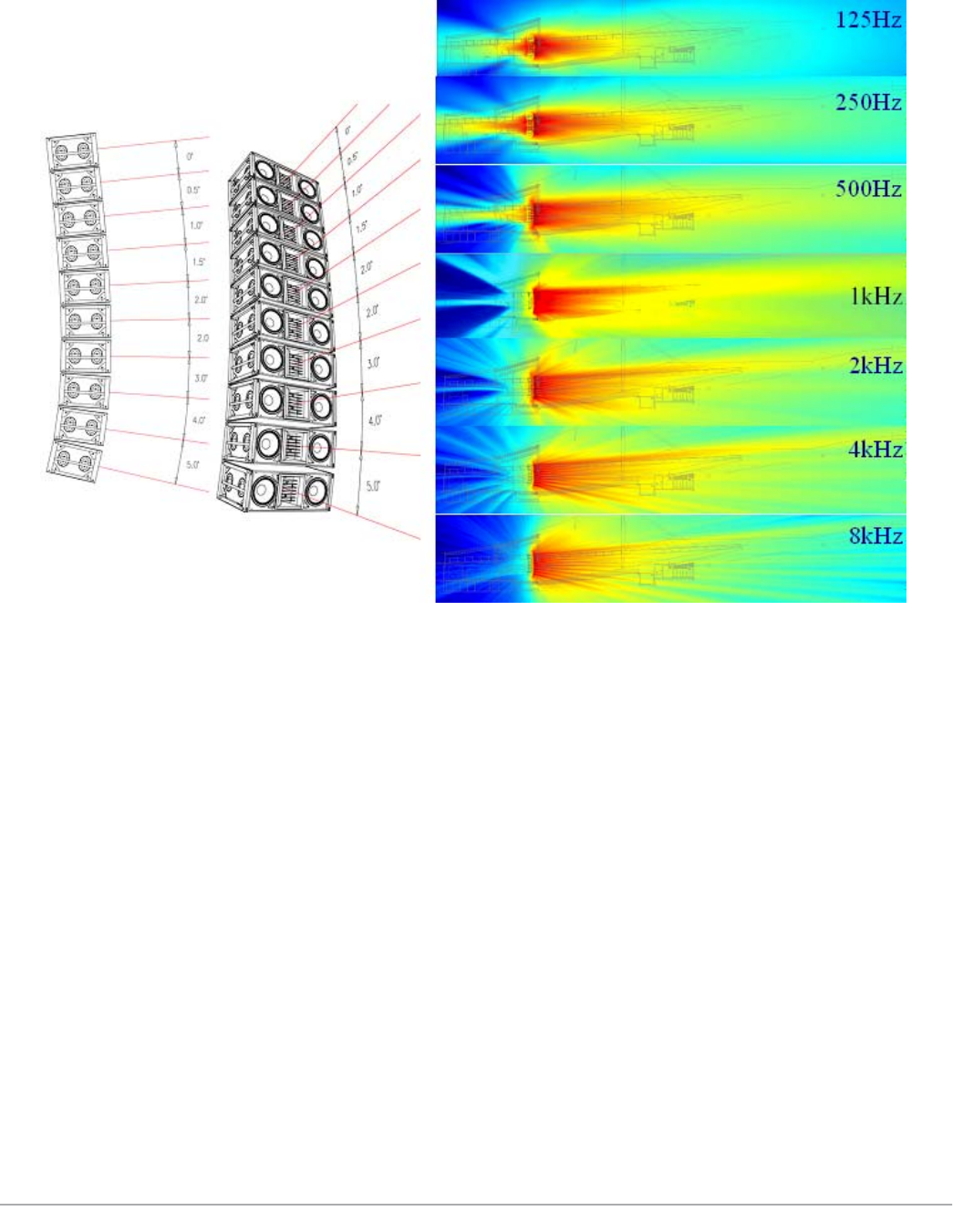
step is to optimize the coverage using the relative
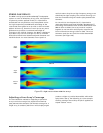
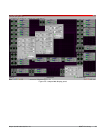
mechanical splay between the array's elements. MAPP
Online is an ideal tool for doing this and determining
what will work best for the application. MAPP can also
help to determine how to break up the electronic drive of
the system using its Virtual SIM feature. For the far field,
a smaller mechanical splay angle achieves superior
throw to compensate for energy lost over distance.
While wave guides provide isolated control over various
coverage areas, the low-frequency section of a line
array still requires mutual coupling—with equal
amplitude and phase—to achieve a narrow beamwidth.
This is important to remember when optimizing the array
with multiple equalization channels. It is best to maintain
a similar or identical equalization in the low-frequency
filters, even though different equalization is being
applied to each zone in the high frequencies.
This is also why gain tapering is not recommended for
line arrays. Adjusting the various zones with an overall
amplitude control for each zone results in the following:
1. Directionality decreases.
2. Overall low-frequency headroom decreases.
3. The length of the line array column is effectively
shortened.
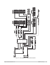
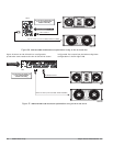
The following is a sample M3D system block diagram
showing one method of driving an array, along with
additional fill loudspeakers and subwoofers. Digital
delays are included to provide a time adjustment to
compensate for the various subsystems and subwoofers
being geometrically out of plane with one another.
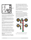
Figure 21. Using vertical splay to adjust a line array’s coverage


