


5
audio interruption. In the third, and preferable case,
supplies that feature voltage foldback allow brief periods
of current-limit without audio interruption; for this reason,
we recommend using such supplies.
The HM-1S does not require tight voltage regulation and
operates down to 35 V although peak SPL values are
reduced. This operating voltage flexibility allows for wir-
ing loss and voltage foldback without interruption or
degradation of the audio signal.
Many high power industrial supplies (15 kWatt) are
available for 19 EIA racks that are suitable for large
installations with equipment rooms. Distribution panels
with branch circuits can be used economically with up to
8 HM-1Ss on a branch. Contact Meyer Sound for in-
formation on tested and approved supplies.
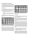
Power Cable Requirements
Each HM-1S draws a maximum of 3 Arms and 5 Apk
from a 48 V power supply at peak SPL. The cabling
between the 48 V supply and the speaker adds resis-
tance to the circuit and produces a voltage drop at the
speaker. Decreasing the voltage at the speaker com-
promises the peak SPL so cable resistance should be
minimized.
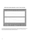
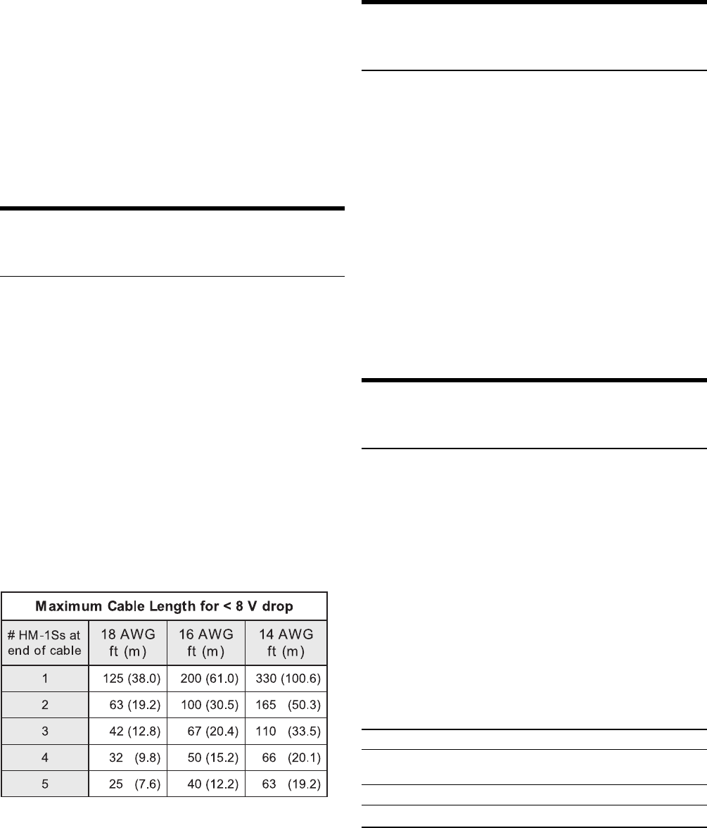
For best sonic performance, avoid voltage drops greater
than 8 V at the speaker. Voltage drops greater than 15
V may cause the speaker to mute or distort. The maxi-
mum round-trip resistance for a cable attached to a
single HM-1S should be no higher than 1.6 Ω, which
keeps the voltage drop below 8 V during the maximum
current draw of 5 Apk.
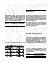
The following table helps select cable gauges for various
cable lengths.
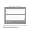
A single HM-1S attached to a 100 ft 18 AWG cable (1.27
Ω total) produces a 6.4 VDC loss at the speaker (41.6 V)
during maximum audio bursts (5 A, 0.5 s). This results in
a small loss in peak SPL.
Audio Input
The HM-1S has an input impedance of 10 kΩ and receives
its audio input signal at a female XLR connector. Pins 2
and 3 carry the input as a differential signal; pin 1 and the
case are connected to the chassis. The power and audio
cables can be jacketed in the same sheath without induc-
ing noise to the input signal.
For best EMI immunity, it is desirable to use a twisted pair
shielded cable with the twisted pair connected to pins 2
and 3, and the shield to pin 1. However, an unshielded
twisted pair cable can be used effectively, even if it is
jacketed with the power cable.
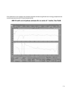
The input is RF and ESD protected, capacitive coupled,
±50 V common mode to ground, +4 dBu nominal, +21 dBu
max. Clipping occurs at the input at 12 Vpk. The Common
Mode Rejection Ratio (CMRR) is greater than 80 dB.
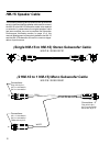
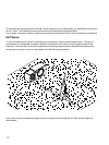
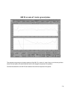
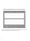
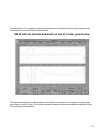
The HM-1S Subwoofer
The low frequency response of an HM-1S can be extended
down to 42 Hz if used with the HM-1S Subwoofer or placed
next to a wall or ceiling (half-space loading). Each HM-1S
can power a subwoofer from the male 3-pin EN3 Sub
output connector on the rear panel. However, depending on
the loading conditions, ample low frequency energy may
be obtained by driving a single subwoofer from two HM-
1Ss, resulting in a correctly-summed mono signal. Cables
for connecting one HM-1S to a subwoofer and two HM-1s
to a single subwoofer are shipped with each HM-1S
Subwoofer.
The addition of one subwoofer increases the maximum
SPL of a single HM-1S by 4 dB (without sub: 116 dB SPL;
with sub: 120 dB SPL). The HM-1S Subwoofer has the
following specifications:
Transducer 10 low frequency cone driver
Enclosure/Finish Medium Density Fiberboard (MDF) /
Oak Veneer (natural or black)
Weight 33 lb (11.0 kg)
Dimensions Height: 17.5; Width: 12.3; Depth: 9.3