


Notes:
1. All equalization circuits
out.
2. 1 kHz input at +4 dBu
3. “A” weighted noise floor
to maximum RMS output
4. Within the operating band
of each channel, maxi-
mum input level is the
minimum worst-case
level achieved before
clipping.
A ground lift switch floats audio
common (XLR connector pin 1) from
the chassis. (Earth and chassis are
always connected for safety.)
A gain switch adjusts for unity gain
with either balanced or unbalanced
input signal connections. (Outputs
remain balanced at all times.)
CP-10S Specifications
Frequency Response
1
20 Hz – 20 kHz ±0.5 dB
Total Harmonic Distortion
2
< 0.01%
Hum and Noise -90 dBV “A” weighted, unbalanced
Dynamic Range
3
110 dB
Inputs
Type Balanced active
Impedance 20k ohms balanced
Level
4
+4 dBu nominal, +20 dBu maximum
Outputs
Type Balanced active push-pull
Impedance 300 ohms, 150 ohms per branch unbalanced
Level +4 dBu nominal, +26 dBu maximum
Controls
Front Panel EQ In/Out, Center Frequency, Bandwidth,
Boost/Cut, Lo and Hi Shelving Cut
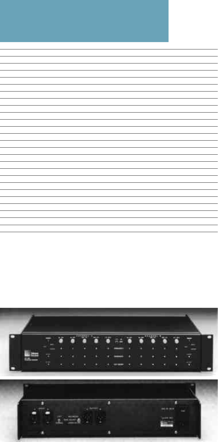
Rear Panel Ground Lift switch, Gain switch,
AC Voltage switch
Indicators
Power Green LED
Ready Green LED
Clip (Input and Output) Red LEDs
Connectors 3-pin XLR male (outputs) and female (inputs)
Power 120/240V AC, 50/60 Hz, rear-panel switchable
Physical
Dimensions 19" W x 3
1
/2" H x 7
1
/2" D standard rack mount
Weight 13 lbs (5.9 kg)
Individual In/Out switches for
each frequency band
Center frequency selection
(10:1 range)
Bandwidth control (0.1 octave
to 1.1 octaves, continuously
variable)
Boost or cut (
±
15 dB)
High and low shelving cut filter
controls
LEDs indicate power status and
gaged. When power to the CP-10S is inter-
rupted, input signals are bypassed directly
to the corresponding outputs.
The front panel may be removed without
affecting control settings, and each equal-
ization stage resides on a separate, gold-
socketed circuit card for ease of service. An
optional smoked plastic security cover dis-
courages tampering in fixed installations.
The clearly marked front panel includes
individual in/out switches for each equal-
ization band, with screwdriver-adjustable
frequency, bandwidth and boost/cut con-
trols. LEDs indicate power status and sig-
nal clipping.
Signal flow through the device is con-
trolled by a delayed relay which allows the
CP-10S circuitry to stabilize before it is en-
Back1Pg .
Next Pg.
Home
Print
Quit