


Notes:
1. All equalization circuits
out.
2. 1 kHz input at +4 dBu
3. “A” weighted noise floor
to maximum RMS output
4. Within the operating band
of each channel, maxi-
mum input level is the
minimum worst-case
level achieved before
clipping.
A ground lift switch floats audio
common (XLR connector pin 1) from
the chassis. (Earth and chassis are
always connected for safety.)
A gain switch adjusts for unity gain
with either balanced or unbalanced
input signal connections. (Outputs
remain balanced at all times.)
CP-10 Specifications
Frequency Response
1
20 Hz – 20 kHz ±0.5 dB
Total Harmonic Distortion
2
< 0.01%
Hum and Noise -90 dBV “A” weighted, unbalanced
Dynamic Range
3
110 dB
Inputs
Type Balanced active
Impedance 20k ohms balanced
Level
4
+4 dBu nominal, +20 dBu maximum
Outputs
Type Balanced active push-pull
Impedance 300 ohms, 150 ohms per branch unbalanced
Level +4 dBu nominal, +26 dBu maximum
Controls
Front Panel EQ In/Out, Center Frequency, Bandwidth,
Boost/Cut, Lo and Hi Shelving Cut
Rear Panel Ground Lift switch, Gain switch,
AC Voltage switch
Indicators
Power Green LED
Ready Green LED
Clip (Input and Output) Red LEDs
Connectors 3-pin XLR male (outputs) and female (inputs)
Power 120/240V AC, 50/60 Hz, rear-panel switchable
Physical
Dimensions 19" W x 3
1
/2" H x 7
1
/2" D standard rack mount
Weight 13 lbs (5.9 kg)
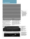
interrupted, input signals are bypassed
directly to the corresponding outputs.
The front panel may be removed without
affecting control settings, and each
equalization stage resides on a separate,
gold-socketed circuit card for ease of
service. An optional smoked plastic security
cover discourages tampering in fixed
installations.
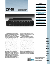
Individual In/Out switches for
each frequency band
Center frequency selection
(10:1 range)
Bandwidth control (0.1 octave
to 1.1 octaves, continuously
variable)
Boost or cut (
±
15 dB)
High and low shelving cut filter
controls
LEDs indicate power status and
The clearly marked front panel includes
individual in/out switches for each equal-
ization band, with separate, calibrated
frequency, bandwidth and boost/cut
controls. LEDs indicate power status and
signal clipping.
Signal flow through the device is
controlled by a delayed relay which allows
the CP-10 circuitry to stabilize before it is
engaged. When power to the CP-10 is
Back1Pg .
Next Pg.
Home
Print
Quit