PAGE 5
TUBE BIAS: (Continued)
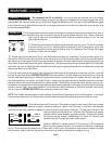
We recommend the 6L6 for reliability: In our many tests and continued use of the currently
available EL34 type power tubes on the market today, we regret to say that they do not appear to be as rugged in construction as the
available 6L6. This is another reason why your
2:100
was shipped with 6L6 power tubes. If you plan to use the EL34’s we suggest
that you keep a full set of tubes and extra fuses with you during all performances in the event of a tube failure occurring when using
the currently available EL34’s.
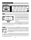
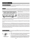
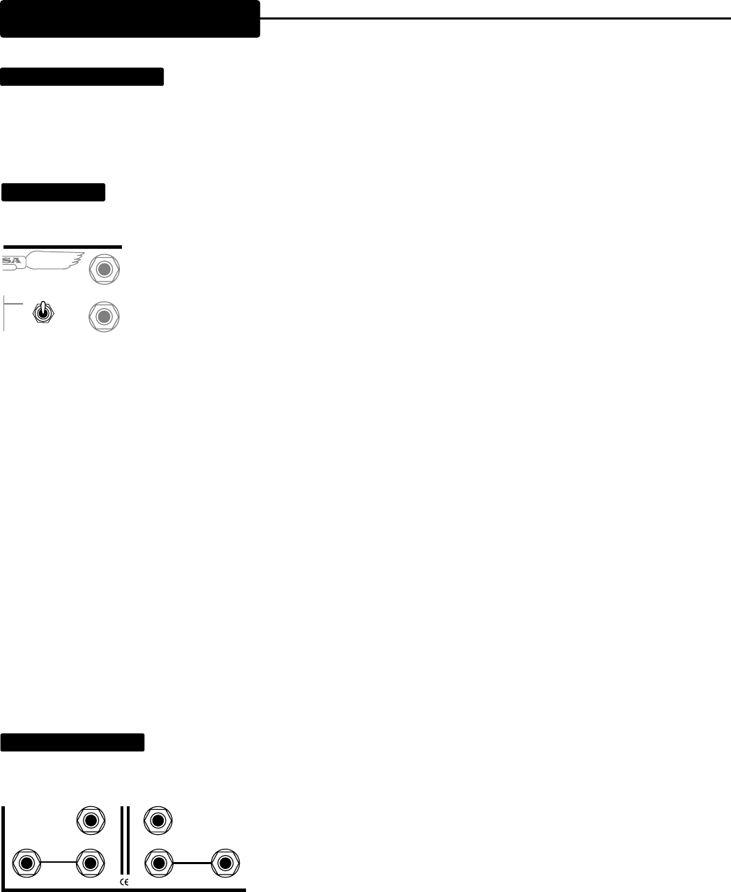
GROUND LIFT:
This mini-toggle switch is extremely useful in reducing the hum and buzz caused by ground loops which occur in
rack installations. Ground loops occur when there is more than one path for grounds between electronic units. There are three main
type of ground loops; each one contributes its own trademark component of buzz or hum. The three
types of ground loops are:
1 ) Grounds being connected via the ground lugs of the power cords on the units. The rule-of-thumb here
is that one and only one unit in a rack should have a connection to the AC power ground; all the other
units in the rack should have their grounds lifted by using 3 to 2 adaptors on their AC plugs. We suggest
grounding the Power amp (no adapter).
2 ) Ground loops occuring because of two or more audio cables connecting two components. The most common solution is to
diconnect the shield from the sleeve connection at one end of some of the inter-connecting cables, so that only one cable between
each device has an intact ground shield. Some experimentation is required to find which cable is best for conducting the ground, and
which cables are best suited to have the special “clipped ground.” We recommend trying the intact-ground cables for the signal path
which flows, say, from an Effects Send jack to an effects unit; and trying the clipped-ground method on the cable which connects the
effects output back into an Effect Return.
3 ) Ground loops created by the physical contact between the metal chassis of the components and the steel rack rails. It is for this
third type of ground loop that the GROUND ISOLATION Switch was provided. This switch effectively lifts the electronic circuit ground
from the metal chassis ground (which otherwise must be done manually by disconnecting a wire inside of the amp.) Here again, the
rule is that one device in your system - and usually only one - needs its circuit ground connected to its metal chassis ground; all others
should be lifted (in other words, disconnected) for quietest operation. (Some effects units provide similar switches; some are con-
structed such that the input ground and the output ground are permanently separated; in other cases, the method used to isolate the
grounds is unclear.) Again, some experimentation is vital to discovering which combination of “lifted” and “grounded” works best in
your rack...and our GROUND ISOLATION Switch makes this process much easier.
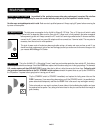
NOTE:
If the
2:100
is operated outside of a rack installation, the switch should generally be set to the Normal position, or squealing,
buzzing and oscillation may occur. Always check this switch before thinking that something has gone wrong with your amp!
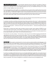
SPEAKER OUTPUTS:
The
2:100
provides one 8 Ohm and two 4 Ohm speaker outputs for each channel. When using a single
8 Ohm speaker or 8 Ohm cabinet on a channel, connect the speaker or cabinet to the 8 Ohm jack. If using two 8 Ohm speakers
(assuming they are wired in parallel) or cabinets on a channel, plug them both into the 4 Ohm jacks. ( The logic here is that two 8 Ohm
loads connected in parallel add up to a 4 Ohm total load.) Mismatching of speaker
impedance will not cause damage or severe loss of power. (Extreme mis-matches
will decrease tube life, however.)
MESA/Boogie
4x12 and 4x10 cabinets come
standard wired to 8 Ohms and are wired in series-parallel.
Some Non-
MESA
4x12 cabinets are wired 16 Ohms using four 16 Ohm speakers.
By wiring all four speakers in parallel, you can reduce the cabinet to an impedance
load of 4 Ohms (assuming the speakers are 16 Ohms each.) Further back in this manual we have included a number of possible
wiring schemes - amps to cabinets, that may be of some use to you when considering how to configure your rig.
REAR PANEL (Continued)
E R I N G
WARNING
:
To reduce risk of fire or electric
shock, Do not remove cover. No user-
serviceable parts inside. Refer
servicing to qualified personnel.
GROUND
SWITCH
LIFT
GROUND
FUSE
6 A
SLO
BLO
I
N
P
U
T
S
NORMAL
4 OHM
8 OHM
CHAN. B CHAN. A
8 OHM
4 OHM
SPEAKERS
SPEAKERS


