REAR PANEL CONTROLS: (Continued)
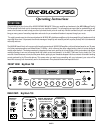
GROUND LIFT / POST & PRE / DIRECT OUT: (Continued)
PRE gives you just the sound of your instrument and no
BIG
BLOCK 750
enhancement so that an engineer can create their own sound with your unprocessed signal at the console. This is very
handy for sound reinforcement applications as the sound you use on stage may be too big with enhanced low end for a large venue
house application.
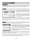
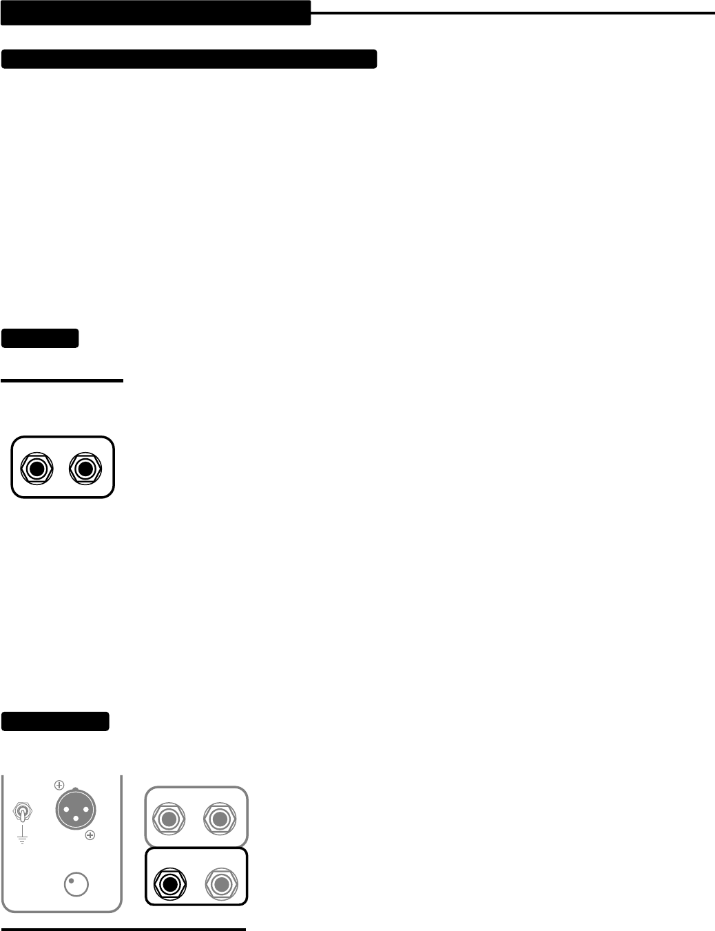
GROUND LIFT: This switch removes the circuit-to-chassis ground connection from the XLR jack. Leave it in the grounded position
(switch down) normally unless you experience a hum when connecting to a console. If you do experience a hum when connecting the
XLR Output to a console, try lifting the ground (switch up) on the circuit. This will usually (but not always) remedy most ground loop
type noise from the signal path. Sometimes it may also be necessary to lift the A.C. Cable Ground also by using a 3-2 ground adapter
to achieve a quiet signal path.
NOTE:
Ground loops can occur in many places in a complex signal path. The DIRECT OUTPUT GROUND LIFT switch is not a cure-
all and therefore should not be expected to remedy every type of ground related problem.
EFFECTS:
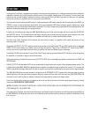
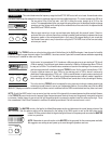
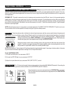
These two jacks provide an interface for external signal processors and they access a point between the preamp and
power section. This wiring scheme creates a Series Effects Loop that is well matched to the input and output impedance of most good
quality processing devices. The jacks used in the loop are switching-type jacks - meaning that when
nothing is inserted into either SEND or RETURN the preamp signal bypasses the jacks. When cables are
inserted the signal path is interrupted and sent through the EFFECTS LOOP.
Because the loop is wired in series, anything you do to the signal here will affect the entire sound of the
amplifier. Therefore we suggest using only the highest possible quality of processing devices and the
best possible low capacitance cables of the shortest possible length.
NOTE:
Cable lengths of 1 foot are best with 3 feet being about the longest desirable length. Using longer interface cables in the series
loop will introduce unwanted capacitance and begin to roll off top end and attack.
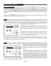
To use the EFFECTS LOOP;
1 ) Connect the SEND jack to your processors’ INPUT.
2 ) Connect the RETURN jack to your processors’ OUTPUT.
3 ) Adjust the dry/wet blend with your processors’ MIX ( WET OUTPUT ) control.
FOOTSWITCH:
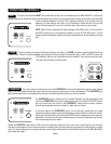
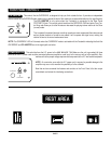
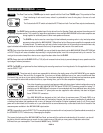
This 1/4” stereo jack accepts the stereo phone plug from the included
BIG BLOCK
Footswitch. Connecting the
FOOTSWITCH via this jack allows remote activation of the OVERDRIVE and SOLO features.
These two features can only be activated when the FOOTSWITCH is connected.
The Front Panel controls for these features are bypassed when the FOOTSWITCH
is disconnected.
PAGE 9
EFFECTS
RETURN SEND
SIMUL STATE BASS AMPLIFIER
TUBE DRIVEN-MOSFET POWER
M-PULSE BIG BLOCK 750
GROUND
LIFT
DIRECT OUTPUT
LEVEL
EFFECTS
RETURN SEND
TUBE DRIVEN-MOSFET POWER
HANDBUILT IN PETALUMA , CALIFORNIA
FOOT
SWITCH
TUNER


