


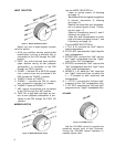
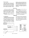
PANLOC BUTTONS
At the bottom front corners are the
PANLOC buttons. After a preamplifier is
installed on the PANLOC shelf, depressing
the PANLOC buttons will lock the preampli-
fier firmly in position. Depressing the PANLOC
buttons a second time (as with a ball-point
pen) will release the preamplifier. The pre-
amplifier can then be slid forward to the
inspection and adjustment position. Releas-
ing the ADJUST position latches allows you to
slide the preamplifier completely out of its
mounting shelf, or back into normal operat-
ing position. The PANLOC system gives you
absolute ease of installation, operation and
maintenance.
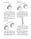
INSTALLATION
The C22 can be installed in conventional
furniture cabinets, custom built installations
or professional relay racks. If the unit is to be
placed on a shelf or table-top, it is recom-
mended that it be housed in a Mclntosh
cabinet. The C22 installs conveniently from
the front of the cabinet by sliding into its
PANLOC shelf.
To support the weight of the C22, the
wood panel used to mount it should be at
least ¼ inch thick.
The C22 installation should allow approxi-
mately 14 inches behind the front panel to
mount the PANLOC shelf and allow for con-
necting wires. To allow sufficient space for
the circulating air, the desirable minimum
internal cabinet dimensions should be 16
inches and 5½ inches respectively.
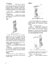
CONNECTING
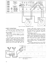
AC CONNECTIONS
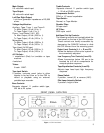
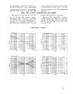
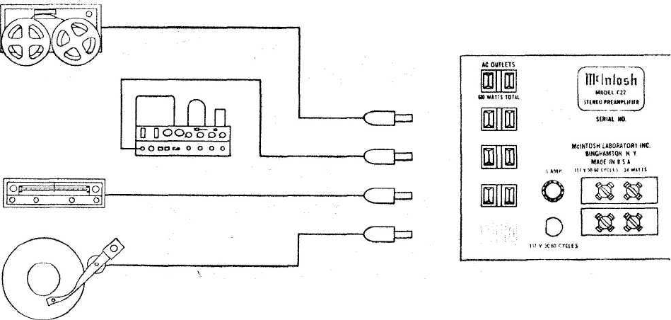
There are five AC outlets on the rear panel
of the C22(See Figurel4.) These receptacles
have a maximum rating of 660 watts total.
The power to the four black receptacles is
controlled by the POWER switch on the front
panel. The red receptacle is not switched.
The red receptacle is used for powering a
turntable or record changer. The receptacle
is not switched so that the turntable power
will not be turned off while the turntable idler
wheel is engaged. The turntable is protected
by this arrangement because it is necessary
to turn off the turntable with its own control
switch so that no damage will result to the
turntable drive system.
Figure 14. A-C Connections.
8