


8
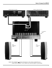
How to Connect the MC602
Caution: The supplied AC Power Cord should not be
connected to the Rear Panel of the MC602
Amplifier until after the Loudspeaker Connections
have been made and the supplied protective
Terminal Connections Cover has been installed.
Failure to observe this could result in Electric
Shock.
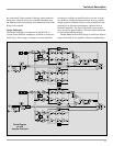
1. For Remote Power Control, connect a power control
cable from the Control Center or Preamplifier Power
Control Out to the MC602 Power Control In.
2. Connect cables from the Balanced Outputs of a McIn-
tosh Preamplifier or Control Center to the MC602 Bal-
anced Inputs.
Note: An optional hookup is to use unbalanced cables.
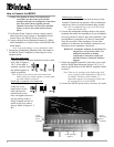
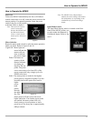
3. Prepare the Loudspeaker Hookup Cables that attach to
the MC602 Power Amplifier by choosing one of the
methods below:
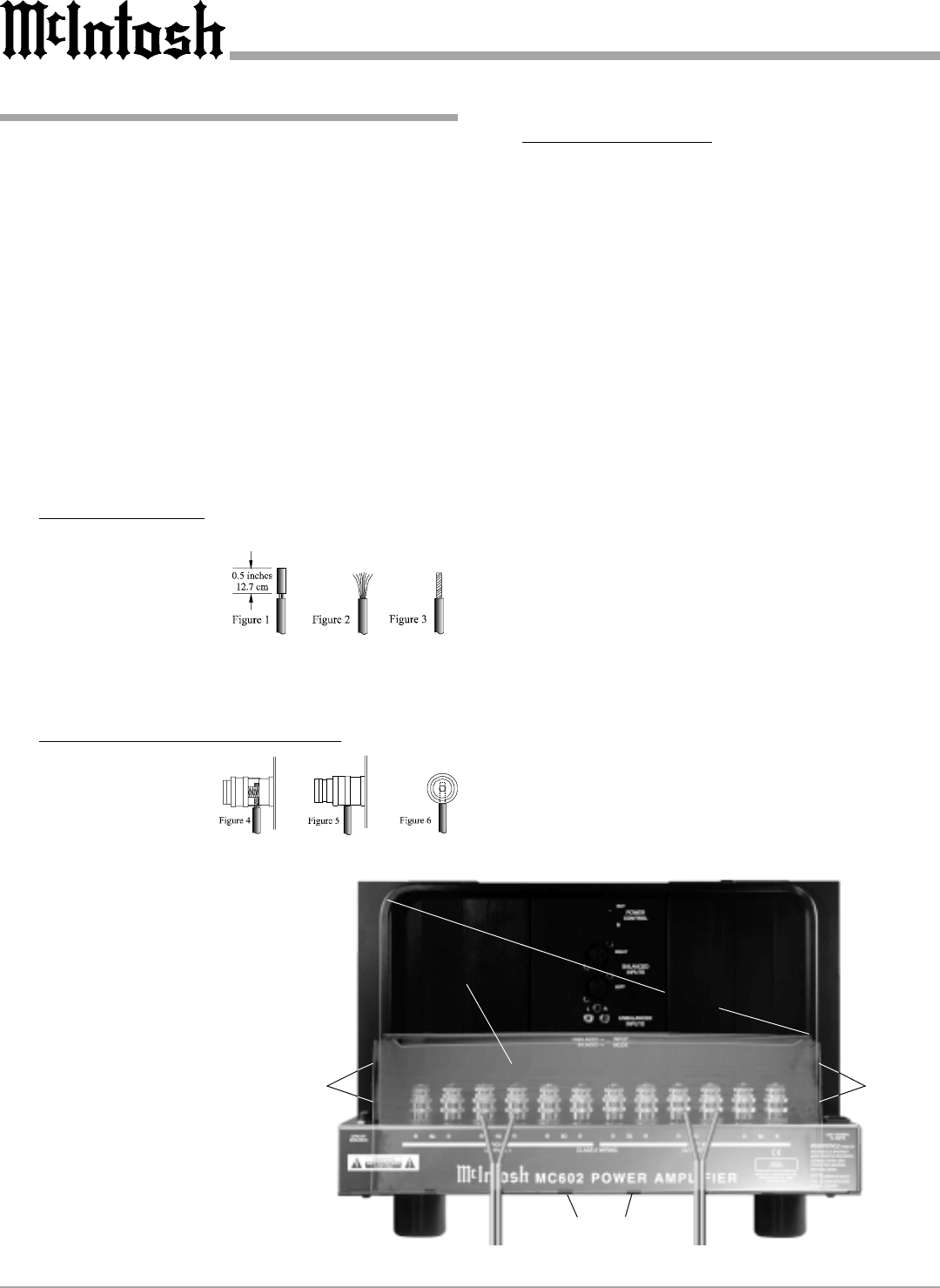
Bare wire cable ends:
Carefully remove sufficient insulation from the cable
ends, refer to figures 1,
2 & 3. If the cable is
stranded, carefully twist
the strands together as
tightly as possible.
Note: If desired, the twisted ends can be tinned with
solder to keep the strands together, or attach spade
lug and/or banana connector.
Spade lug or prepared wire connection:
Insert the spade lug
connector or pre-
pared section of the
cable end into the
terminal side access
hole, and tighten the termi-
nal cap until the cable is
firmly clamped into the ter-
minal so the wires cannot
slip out. Refer to figures 4, 5
& 6.
Banana plug connection:
Insert the banana plug into the hole at the top of the
terminal. Tighten the top portion of the terminal post
and the set screw to secure the banana plug in place.
Note: The use of Banana Plugs is for use in the United
States and Canada only.
4. Connect the loudspeaker hookup cables to the output
terminals that match the impedance of your loudspeak-
ers, being careful to observe the correct polarities. Out-
put impedance connections of 2 ohms, 4 ohms and 8
ohms are provided. If the impedance of your loud-
speakers is in-between the available connections, use
the nearest lower impedance connection.
WARNING: Loudspeaker terminals are hazardous live
and present a risk of electric shock. For
additional instruction on making
Loudspeaker Connections contact your
McIntosh Dealer or McIntosh Technical
Support.
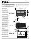
5. Attach the supplied Terminal Connections Cover with
the four Philip Head Mounting Screws (10-32 x 1/2
inch) to the Rear Panel of the MC602 Amplifier. Refer
to figure 7.
Note: There are six openings on the bottom edge of the
cover to allow for the Loudspeakers Cable to exit
the MC602. The Rear Chassis Handle (U
shaped) has tapped screw openings on both sides
for securing the cover to the MC602.
6. Connect the MC602 power cord to an active AC outlet.
Terminal
Connections
Cover
Cover
Mounting
Screw
Locations
Cable Openings
Rear
Chassis
Handle
Cover
Mounting
Screw
Locations
Figure 7