


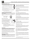
9
How to Connect
How to Connect for Left, Center and Right
Channels
Note: The remaining Amplifier Loudspeaker Terminals
should not be connected to another Loudspeaker.
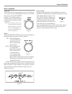
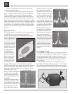
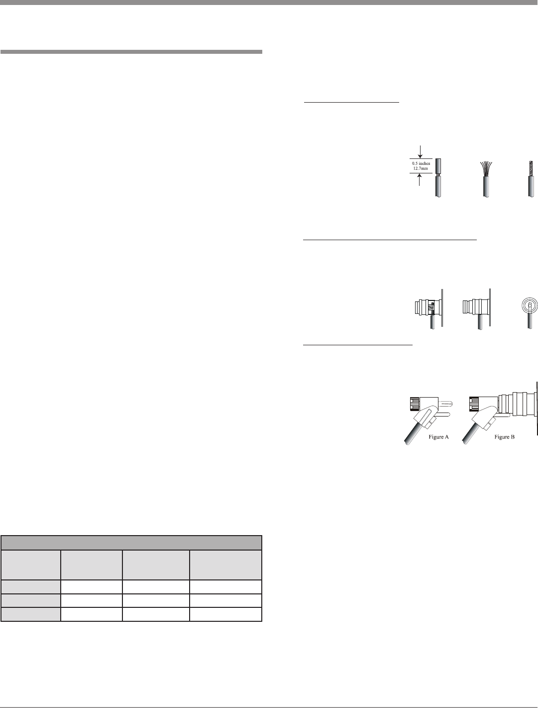
6. Prepare the Loudspeaker Hookup Cables that attach to
the Amplifier by choosing one of the methods below:
Bare wire cable ends:
Carefully remove sufficient insulation from the cable
ends, refer to figures 1, 2 & 3. If the cable is strand-
ed, carefully twist the strands together as tightly as
possible.
Note: If desired, the
twisted ends can
be tinned with
solder to keep
the strands together, or attach spade lug and/or
banana connector.
Spade lug or prepared wire connection:
Insert the spade lug connector or prepared section
of the cable end into the terminal side access hole,
and tighten the terminal cap until the cable is firmly
clamped into the
terminal so the wires
cannot slip out. Refer
to figures 4, 5 & 6.
Banana plug connection:
Insert the banana plug into the hole at the top of the
terminal. Refer to figures A and B.
Note: Banana
Plugs are
for use in
the United
States and
Canada
only.
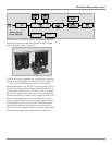
7. Connect the Loudspeaker hookup cables from a single
Loudspeaker to the output terminals that match the
impedance of OUPUT 1, being careful to observe the
correct polarities. Output impedance connections of 2
ohms, 4 ohms and 8 ohms are provided. If the Loud-
speaker’s impedance is in-between the available con-
nections, use the nearest lower impedance connection.
Refer to “General Information” Note 5 on page 3 for
additional information.
WARNING: Loudspeaker terminals are hazardous live
and present a risk of electric shock.
8. In a similar manner, connect a Loudspeaker to OUT-
PUT 2 and connect the remaining Loudspeaker to
OUTPUT 3.
9. Connect the MC303 Power Cord to a live AC outlet.
Caution: The supplied AC Power Cord should not be
connected to the Rear Panel of the MC303
Amplifier until after the Loudspeaker Connec-
tions have been made. Failure to observe this
could result in Electric Shock. For additional
instruction on making Loudspeaker Connec-
tions contact your McIntosh Dealer or McIn-
tosh Technical Support.
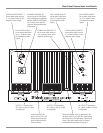
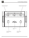
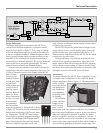
The connection instructions below, together with the
MC303 Connection Diagram located on the separate folded
sheet “Mc1B, is an example of a typical audio/video sys-
tem. Your system may vary from this, however the actual
components would be connected in a similar manner. For
additional information refer to “Connector and Cable In-
formation” on page 4.
1. For Remote Power Control, connect a power control ca-
ble from the A/V Control Center or Preamplifier Power
Control Out to the MC303 POWER CONTROL IN.
2. Connect a second power control cable from the MC303
POWER CONTROL OUT to the Left and Right Sur-
round Channel Power Amplifier Power Control In.
3. Connect cables from the Balanced Outputs of the A/V
Control Center or Preamplifier (Left, Center and Right
Front Channels) to the MC303 BALANCED INPUTs
(1-3).
Note: An optional hookup is to use the UNBALanced IN-
PUTS with unbalanced cables instead of balanced.
However, both type of connections for a given Input
should not be used at the same time.
4. Connect cables from the Balanced Outputs of the A/V
Control Center or Preamplifier (Surround Channels) to
the Left and Right Surround Channel Power Amplifier.
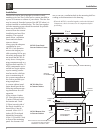
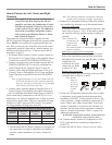
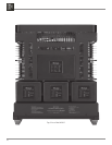
When connecting Loudspeakers to the MC303 it is very
important to use cables of adequate size, so there is little to
no power loss in the cables. The size is specified in Gauge
Numbers or AWG (American Wire Gauge). The smaller
the Gauge number, the larger the wire size:
5. This McIntosh MC303 Power Amplifier is designed for
the connection of a single Loudspeaker per amplifier
channel, with an impedance of 2 ohms, 4 ohms or 8
ohms.
Figure 1
Figure 2 Figure 3
Figure 4 Figure 5 Figure 6
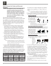
Loudspeaker Cable Distance vs Wire Gauge Guide
Loudspeaker
Impedance
25 feet
(7.62 meters)
or less
50 feet
(15.24 meters)
or less
100 feet
(30.48 meters)
or less
2 Ohms
12AWG 10AWG 8AWG
4 Ohms
14AWG 12AWG 10AWG
8 Ohms
16AWG 14AWG 12AWG