


6
Installation of Tubes and Tube Cover
Caution: To prevent electrical shock make sure that
the AC POWER CORD IS NOT CONNECT-
ED TO THE MC275 when inserting or
removing Tubes, as there are hazardous volt-
ages present at the pins of the Tube Sockets.
Your MC275 has gone through an extensive series of
performance tests during the manufacturing process. The
MC275 is supplied with the actual Tubes that were used
to test and confirm the performance of this amplifier. To
protect the Vacuum Tubes from possible shipping damage,
they are packed in four layers of foam and placed into the
Tube Cover. It is secured to the MC275 Chassis.
Note: Gloves or a soft cloth will prevent “ fingerprinting” of
the Tubes during their installation.
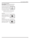
1. Orient the MC275 so the Front Panel is facing you.
2. Remove the Tube Cover from the MC275 Chassis by
lifting up on both sides. Refer to figure 1.
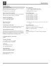
3. Orient the Tube Cover with the top side down so the
foam containing the Tubes is accessible. Refer to fig-
ure 2.
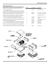
4. Remove the first layer of foam to expose the Tubes.
Refer to figure 3.
5. Carefully remove the Tubes from the remaining pieces
of foam and temporarily place them in a safe location.
6. Remove the remaining foam from the Tube Cover and
retain all four pieces for possible future use.
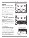
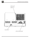
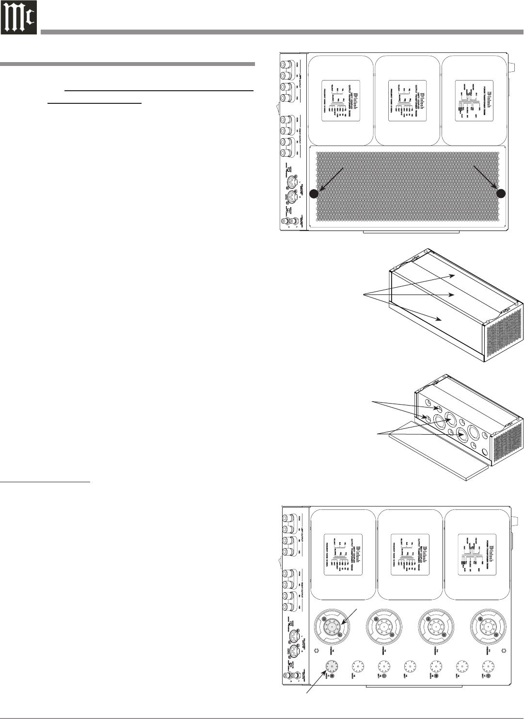
The MC275 Chassis has nomenclature screened on it to
specify both the circuit location and Tube Type for each
channel. Refer to figure 4.
Note: It is extremely important to insert the Tubes in the
correct location.
Power Output Tubes:
1. Orient the Chassis so the Front Panel of the Amplifier is
facing you.
2. Locate a KT88 or 6550 Power Output Tube.
3. On the top left side of the amplifier, locate the Tube
Socket that has the nomenclature V8 KT88/6550 next
to it on the chassis.
4. Orient the Tube so the key on the base of the Tube
is aligned with the corresponding key on the Tube
Socket.
5. Carefully insert the Tube into the socket until the base
of the Tube is fully seated in the Tube Socket.
6. Repeat the above the steps for the remaining 4 Power
Output Tubes.
There are two different types of Small Signal Tubes
(12AX7A and 12AT7) used in each channel. Tube type can
be found on the outside of the Tube. The MC275 will not
function if they are inserted into the wrong socket.
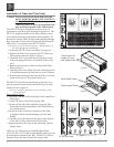
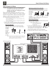
Figure 1
Tube Cover
Tinnerman Clip Fasteners
Figure 2
Tube Cover with
Layers of Foam
and Tubes inside
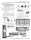
Figure 3
Power Output Tubes
Small Signal Tubes
Figure 4
V8 KT88/6550 Tube
V1 12AX7A Tube