


8
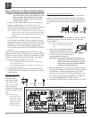
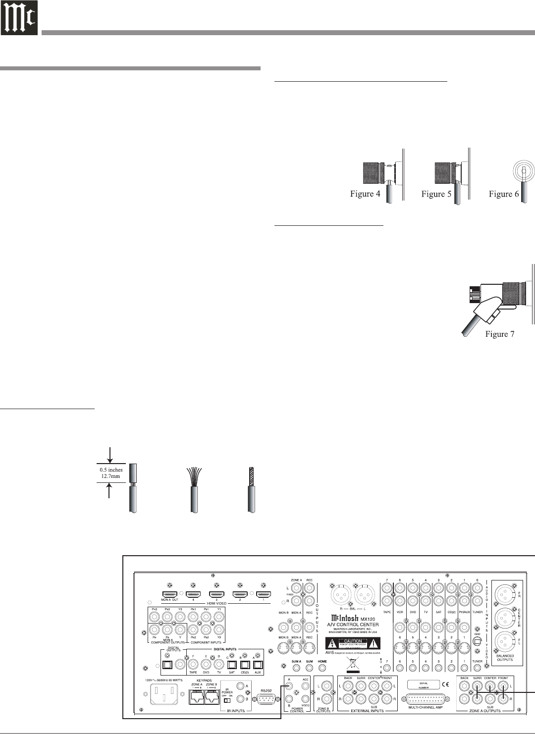
Spade lug or prepared wire connection:
Insert the spade lug connector or prepared section of the
cable end into the terminal side access hole, and tighten
the terminal cap until the cable is firmly clamped into the
terminal so the wires cannot slip out. Refer to figures 4, 5
& 6.
Banana plug connection:
Tighten the top portion of the terminal post and insert the
banana plug into the opening at the top of the terminal.
Refer to figure 7.
Note: The use of Banana Plugs is for use
in the United States and Canada
only.
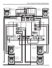
4. Connect the Loudspeaker Hookup
Cables from the MC205 OUTPUT
Terminals to the Loudspeakers,
being careful to observe the correct
polarities and channel designation.
WARNING: Loudspeaker terminals are hazardous live
and present a risk of electric shock. For ad-
ditional instruction on making Loudspeaker
Connections contact your McIntosh Dealer
or McIntosh Technical Support.
5. Place the IMPEDANCE Switch to the position (4 ohm
or 8 ohm) that matches the impedance of the connected
Loudspeakers. In the event that some of the Loud-
speakers in the system are of different impedance, use
the impedance of the Left and Right Front Loudspeak-
ers to set the IMPEDANCE Switch position.
6. Connect the MC205 Power Cord to an active AC outlet.
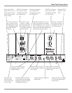
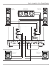
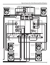
How to Connect for a Five Channel System
Caution: The supplied AC Power Cord should not be con-
nected to the Rear Panel of the MC205 Power Am-
plifier until after the Loudspeaker Connections
have been made. Failure to observe this could
result in Electric Shock.
1. Connect Audio Cables from the Zone A Unbalanced
Outputs of a McIntosh A/V Control Center to the
MC205 INPUTS (Channels 1-5), making sure to match
up the channel identifications between both units.
Note: In place of the Unbalanced Audio Cables, Balanced
Cables may be used.
2. Connect a power control cable from the McIntosh
A/V Control Center Zone A Power Control Out to the
MC205 POWER CONTROL ZA.
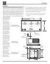
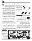
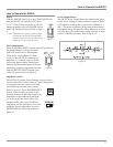
When connecting Loudspeakers to the MC205 it is very
important to use cables of adequate size, so there is little to
no power loss in the cables. The size is specified in Gauge
Numbers or AWG (American Wire Gauge). The smaller
the Gauge number, the larger the wire size:
If your loudspeaker cables are 50 feet (38.1m) or less,
use at least 14 Gauge.
If your loudspeaker cables are 100 feet (76.2m) or less,
use at least 12 Gauge.
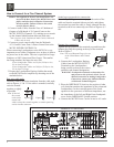
3. Prepare the Loudspeaker Hookup Cables that attach
to the MC205 Power Amplifier by choosing one of the
methods below:
Bare wire cable ends:
Carefully remove sufficient insulation from the cable ends,
refer to figures 1, 2 & 3. If the cable is stranded, carefully
twist the strands
together as tightly
as possible.
Note: If desired,
the twisted
ends can be
tinned with
solder to keep the strands together, or attach spade lug
and/or banana connector.
Figure 1
Figure 2
Figure 3
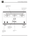
McIntosh A/V Control Center