


4
Table of Contents
General Notes
Caution: The MC1201 Amplifier weight is 147 pounds
(66.7 kilograms). It requires two or more persons
to safely handle when moving the amplifier.
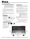
1. The following Connecting Cable is available from the
McIntosh Parts Department:
Power Control Cable Part No. 170-202
Six foot, 2 conductor shielded, with two 1/8 inch stereo
mini phone plugs.
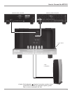
2. For additional connection information, refer to the owners
manual(s) for any component(s) connected to the MC1201.
3. The MC1201 mutes the speaker output for approximately two
seconds when first turned on.
4. It is very important that loudspeaker cables of adequate size
be used, so that there will be no power loss. The size is
specified in Gauge Numbers or AWG, (American Wire Gauge).
The smaller the Gauge number, the larger the wire size:
If your loudspeaker cables are 50 feet (38.1m) or less,
use at least 14 Gauge.
If your loudspeaker cables are 100 feet (76.2m) or less,
use at least 12 Gauge.
5. Pin configuration for the XLR Balanced Input connectors on
the MC1201: PIN 1: Shield or ground
PIN 2: + input
PIN 3: - input
6. In the event that the MC1201 over heats, due to improper
ventilation and/or high ambient temperature, the protection
circuits will activate. The Front Panel Power Guard LED will
continuously indicate ON and the audio will be muted. When
the MC1201 has returned to a safe operating temperature,
normal operation will resume.
7. The MC1201 incorporates the very latest in Fully Double
Balanced Circuitry. As a result, the Loudspeaker Negative
Connections are above chassis ground. Do not combine any
connections together, ground them or connect with another
MC1201.
Performance Features
Introduction
· Power Output
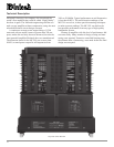
The MC1201 is a Power Amplifier with a capability of
1,200 watts into 2, 4 or 8 ohm speakers with less than
0.005% distortion.
· Full Balanced Circuity
The MC1201 is fully balanced from inputs to outputs. It
consists of two matched power amplifiers operating in
push-pull with their outputs combined in a McIntosh
Autoformer. The double balanced configuration cancels
virtually all distortion.
· Power Guard
The patented McIntosh Power Guard circuit that prevents
the amplifier from being overdriven into clipping, with its
harsh distorted sound that can also damage your valuable
loudspeakers.
· Sentry Monitor and Thermal Protection
McIntosh Sentry Monitor power output stage protection
circuits ensure the MC1201 will have a long and trouble
free operating life. Built-in Thermal Protection Circuits
guard against overheating.
· Patented Autoformer
McIntosh designed and manufactured Output Autoformers
provide an ideal match between the amplifier output stages
and speaker loads of 2, 4 and 8 ohms. The Autoformers
also provide perfect DC protection for your valuable loud-
speakers.
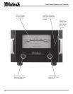
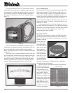
· Illuminated Power Meter
The Illuminated Power Output Watt Meter on the MC1201
is peak responding, and indicates the true power output of
the amplifier. The Peak Watt Hold Mode allows the meter
to temporarily stay at the highest power output and then
slowly decay.
Now you can take advantage of traditional McIntosh stan-
dards of excellence in the MC1201 Power Amplifier. The
1,200 watt high current output will drive any high quality
loudspeaker system to its ultimate performance. The
MC1201 reproduction is sonically transparent and abso-
lutely accurate. The McIntosh Sound is The Sound of the
Music Itself.
Safety Instructions ............................................................ 2
Thank You and Please Take a Moment............................. 3
Technical Assistance and Customer Service .................... 3
Table of Contents and General Notes ............................... 4
Introduction ...................................................................... 4
Performance Features ....................................................... 4
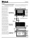
Dimensions ....................................................................... 5
Installation ........................................................................ 6
Rear Panel Connections and Switch ................................. 7
How to Connect ................................................................ 8
Front Panel Displays and Controls ................................. 10
How to Operate............................................................... 11
Technical Description ..................................................... 12
Notes ............................................................................... 16
Specifications ................................................................. 18
Packing Instruction ......................................................... 19