


4
Performance Features
Introduction and Performance Features
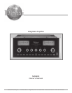
Introduction
••
••
• Power Output
The MA6900 consists of two separate power amplifier
channels, each capable of 200 watts into 2, 4 or 8 ohm
speakers with less than 0.005% distortion.
••
••
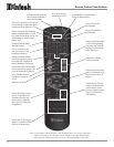
• Electronic Input Switching
Digital Logic integrated circuits drive Electromagnetic
Switches on all six inputs and operating functions for reli-
able, noiseless, distortion free switching.
••
••
• Power Guard
Both channels include the patented McIntosh Power Guard
circuit that prevents the amplifier from being overdriven
into clipping, with its harsh distorted sound that can also
damage your valuable loudspeakers.
••
••
• Sentry Monitor and Thermal Protection
McIntosh Sentry Monitor power output stage protection
circuits ensure the MA6900 will have a long and trouble
free operating life. Built-in Thermal Protection Circuits
guard against overheating.
••
••
• Patented Autoformers
McIntosh designed and manufactured Output Autoformers
provide an ideal match between the amplifier output stages
and speaker loads of 2, 4 and 8 ohms. The Autoformers
also provide perfect DC protection for your valuable loud-
speakers.
••
••
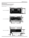
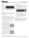
• Illuminated Power Meters
The Illuminated Power Output Meters on the MA6900 are
peak responding, and indicate the power output of the am-
plifier.
Now you can take advantage of traditional McIntosh stan-
dards of excellence in the MA6900 Integrated Amplifier.
Two 200 watt high current output channels will drive any
high quality loudspeaker system to its ultimate perfor-
mance and the flexible Preamplifier Selection provides for
hookup and control of various input sources. The MA6900
reproduction is sonically transparent and absolutely accu-
rate. The McIntosh Sound is “The Sound of the Music It-
self.”
Important Information
1. The following parts are available from the McIntosh Parts
Department:
Power Control Cable Part No. 170-202
Six foot, 2 conductor shielded, with two 1/8 inch stereo
mini phone plugs.
Jumper Plugs Part No. 117-781
RCA Phono Jumpers, 14mm center spacing.
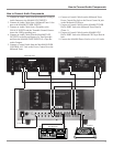
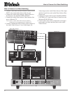
2. For additional connection information, refer to the owner’s
manual(s) for any component(s) connected to the MA6900.
3. The MA6900 mutes the speaker outputs for approximately two
seconds when first turned on.
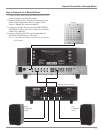
4. It is very important that loudspeaker cables of adequate size
be used, so that there will be no power loss. The size is
specified in Gauge Numbers or AWG (American Wire Gauge).
The smaller the Gauge number, the larger the wire size:
If your loudspeaker cables are 50 feet (38.1m) or less,
use at least 14 Gauge.
If your loudspeaker cables are 100 feet (76.2m) or less,
use at least 12 Gauge.
5. In the event that the MA6900 over heats, due to improper
ventilation and/or high ambient temperature, the protection
circuits will activate. The Front Panel Power Guard LEDs
will continuously indicate ON and the audio will be muted.
When the MA6900 has returned to a safe operating
temperature, normal operation will resume.
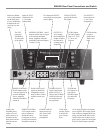
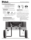
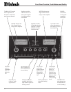
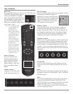
XLR Connectors
Below is the Pin configuration for the XLR Balanced Input
Connectors on the MA6900. Refer to the diagram for con-
nection:
PIN 1: Shield/Ground
PIN 2: + Input
PIN 3: - Input
Power Control and Trigger Connectors
The MA6900’s Power Control Outputs provide a 5 volt
signal. Use a 1/8 inch stereo mini
phone plug to connect to the
Power Control Input on other
McIntosh Components.
Data Port Connector
The MA6900’s Data Port Output provides Remote Control
Signals. Use a 1/8 inch stereo
mini phone plug to connect to the
Data Port Inputs on McIntosh
Source Units.
Connector Information
Positive
N/C
Ground
Data Signal
N/C
Ground
Pin 1
Pin 2
Pin 3