GROUND POUNDER
DRIVE
GROUND POUNDER
DRIVE
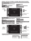
GPV800.2 / GPV1100.2 / GPV3500.2 2 CHANNEL AMPLIFIER APPLICATIONS
3
FULL RANGE MONO
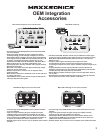
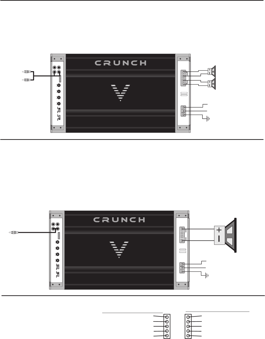
This is the most basic application for the GROUND POUNDER Series 2 channel
3. Crossover frequency control checklist:
amplifiers.
N/A for full range operation.
4. Line Level:
1. Interconnect cable checklist:
Connect the LINE INPUTS to the Radio/CD with good quality RCA cables. Refer to the section “Setting up systems after installation for best performance”.
2. Crossover Switch:
The X-OVER switch must be in the FULL position.
NOTE: Minimum final loudspeaker impedances:
The MODE switch must be in the STEREO position.
4 &-2-Ohms stereo mode or 4-Ohms mono mode
Switch setting checklist:
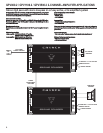
This application illustrates the basic mono bridging method for all Crunch 2 channel
- The X-OVER switch must be in the FULL position.
amplifiers.
- The MODE switch must be in the MONO position.
Interconnect cable checklist:
Crossover frequency control setting checklist:
A MONO signal source is required, such as would be available from the mono sub bass
N/A for full range operation.
output of an active crossover, whether stand alone, or built into a head unit or equalizer.
TIP:
Important:
If you are using the mono sub bass output of an active crossover, there is nothing
Do not be tempted to connect the hot, or positive outputs, from any source
wrong with switching in the low pass filter in these amplifiers for a steeper low pass roll-off.
together to obtain a mono signal, as this could very well damage the output stage of that
source.
It is necessary to feed the SAME signal to both left and right inputs via a Y-adapter RCA
Minimum final loudspeaker impedance:
cable. Connect the mono speaker positive terminal to the LEFT +, and its negative
- 4-Ohms mono.
terminal to RIGHT -.
FULL RANGE STEREO
FULL RANGE
MONO SPEAKER
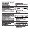
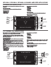
The HIGH LEVEL inputs are used when the radio/CD player does not have RCA cable outputs. You can connect the radio/CD player speaker wires directly
to the amplifier via the high Level Inputs.
GRAY: CH 1 Speaker Input +
BROWN: CH 1 Speaker input -
Black: Chassis Ground
GREEN: CH 2 Speaker Input -
White: CH 2 Speaker Input +
ORANGE: CH 3 Speaker Input +
PINK: CH 3 Speaker input -
Black: Chassis Ground
BLUE: CH 4 Speaker Input -
YELLOW: CH 4 Speaker Input +
Use this connector for 2 CH amplifiers
Use both connectors for 4 CH amplifiers
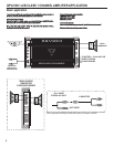
REMOTE TURN-ON
CHASSIS GROUND
TO BATTERY + 12 volts VIA FUSE
+ - gnd - +
HI INPUT
5V 0.2V 0dB 12dB 60Hz 1.2KHz 30Hz 250Hz
LEVEL BASS EQ HPF LPF
FULL LPF HPF MONO STEREO
X-OVER MODE
LINE OUT LINE INPUT
L
L
R
R
POWER INPUT
SPEAKER OUTPUT
BRIDGED
- LEFT + - LEFT +
FUSE
GND REM +12V
REMOTE TURN-ON
CHASSIS GROUND
TO BATTERY + 12 volts VIA FUSE
+ - gnd - +
HI INPUT
5V 0.2V 0dB 12dB 60Hz 1.2KHz 30Hz 250Hz
LEVEL BASS EQ HPF LPF
FULL LPF HPF MONO STEREO
X-OVER MODE
LINE OUT LINE INPUT
L
L
R
R
POWER INPUT
SPEAKER OUTPUT
BRIDGED
- LEFT + - LEFT +
FUSE
GND REM +12V
FULL RANGE
SPEAKERS
FULL RANGE
STEREO LINE INPUT
FULL RANGE
MONO LINE INPUT
VIA Y-ADAPTER
FROM MONO SOURCE


