


10 Matrox RG Series – User Guide
5
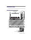
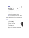
Connect your audio devices
(optional)
Your unit has 2 input and 2 output audio
connectors. The 2 input connectors are
Line
in
() and
Microphone
(). The 2
output audio connectors are
Headphones
() and
Line out
( ). All audio
connectors support stereo jack connectors.
The
Line out
connector also supports
SPDIF
(Sony/Philips Digital Interface Format) mini-
plug optical connectors.
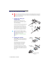
To connect an audio device to your unit:
a
Plug one end of your audio cable into the audio connector on your unit.
b
Plug the other end of the cable in your audio device. For information on the type of
connector supported by your audio device, see its documentation.
Your Matrox product is now installed. Restart your computer, and install your Matrox software.
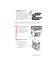
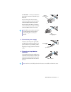
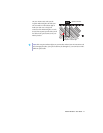
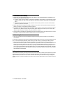
Verifying your interface connection
To check your interface connection, your computer and your ATC RG unit must be on.
On the bracket of your interface card, make
sure both the transmission (
TX
) and
reception (
RX
) indicator lights are green.
If the reception indicator is red and you have
separate optical cables, switch the cables in
the optical connector of your Matrox
product.
If the transmission indicator is red, your
optical connector may be loose. Make sure
your optical connector is firmly in place by
pushing it into its housing. If the light doesn’t change to green, contact your Matrox
representative.
Audio connector
(SPDIF/Stereo)
Note:
If you’re using the headphone connector at the front of your unit, the line-out
connector at the back of the unit is muted.
Reception indicator light
Optical connector
Transmission indicator light