Page 2
STATEMENT Set-up Manual
Introduction
System Set-up
Room Acoustics
Troubleshooting
Contents
2
2
6
8
Introduction
Congratulations! You are about to experience the
highest resolution, most dynamic, extended sound-
stage system in the galaxy, the Statement!
The Martin-Logan STATEMENT represents the
culmination of an intensive, dedicated group research
program directed toward establishing a world class
reference system utilizing leading-edge technology,
without compromising durability, reliability, craftsman-
ship, or aesthetic design.
As a result of our continuous research and develop-
ment program here at Martin-Logan, we decided that it
was time to incorporate some of our latest technolo-
gies into a reference product.
System Set-up
ChecklistChecklist
ChecklistChecklist
Checklist
The Statement system consists of the following items:
2 - electrostatic panels mounted in frames
2 - electrostatic panel pedestals with uprights
2 - interface modules
4 - interface riser blocks
2 - woofer columns
2 - crossover modules*
2 - crossover power supplies*
1 - toolkit
4 - power cords*
* Add two more if system is balanced.
Before setting-up the system, please make note that
odd serial numbers for all components (woofer tower,
stator, interface, crossover, power supply (example:
XICL001)) are matched for use as the right channel,
while even serial numbers for all components are
matched for the left channel.
WW
WW
W
oofer Assembliesoofer Assemblies
oofer Assembliesoofer Assemblies
oofer Assemblies
The woofer assemblies are connected to the amplifier
via either the 5-way binding posts or screw terminals on
the backplate of the woofer column. As can be seen from
the back panel of the Statement woofer, the signal
connectors are strapped in such a way that you can use
one amplifier out of the box.
If you desire or require double amplification, the electronic
crossover modules have dual, low-level, low-pass,
outputs. By removing the straps on the woofer backplate
you can directly access, via one set of 5-way binding
posts, two woofers at a time. Hence you are able to use
two bass amplifiers. This option is available for the
consideration of amplifiers which do not perform their best
into a 2 ohm load. When using two amplifiers, each one
will see only a 4 ohm load.
Electrostatic PElectrostatic P
Electrostatic PElectrostatic P
Electrostatic P
anel Assembliesanel Assemblies
anel Assembliesanel Assemblies
anel Assemblies
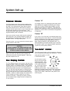
The electrostatic panel assemblies should first be
assembled mechanically. The method of assembly
consists of setting the pedestal on the floor then sliding
the left and right upright braces on to their hidden
fasteners. Observe figure 1. Next, bring the electrostatic
panel assembly to the braces and attach via the hidden
fasteners. Finally, attach the interface riser blocks via the
hidden fasteners and install the interface module on-top
of the risers.


