


Page9
Monolith III User's Manual
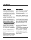
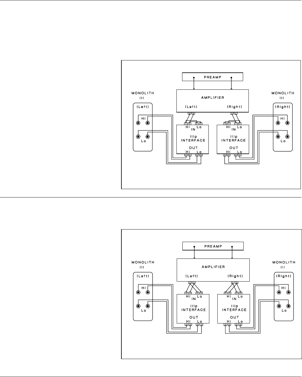
Please take note of the jumpers installed
across the binding posts of the IIIp INTER-
FACE
..
..
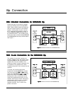
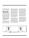
. These jumpers attach the high-pass
and the low-pass sections of the interface
together. Leaving these in place, connect
the (+) wire from your amplifier to either of
the red AMPLIFIER SIGNAL binding posts of
the Interface and the (-) wire to either of the
black posts. Next, connect the IIIp INTERFACE
to the MONOLITH III with the provided cables.
See
Figure 1.
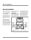
This method of connection replaces the
jumpers installed across the binding posts
of the IIIp INTERFACE with individual runs of
speaker wire from your amplifier. This
doubles the signal carrying conductors from
the amplifier to the speaker thus, direct-
coupling each portion of the crossover to the
amplifier.
To bi-wire you must first remove the
jumpers from the IIIp INTERFACE. Connect
one set of wires to the
HI+HI+
HI+HI+
HI+ and
HI-HI-
HI-HI-
HI- binding
posts of the IIIp INTERFACE. Then connect a
second set of wires to the
LO+LO+
LO+LO+
LO+ and
LO-LO-
LO-LO-
LO-
binding posts. Next, connect both sets of
wires to the appropriate terminals on your
amplifier. See
Figure 2
. Please take care to
connect both (+) wires to the (+) amplifier
terminals and both (-) wires to the (-)
amplifier terminals. This is known as a
parallel connection.
TWO: Bi-wire Connection for the TWO: Bi-wire Connection for the
TWO: Bi-wire Connection for the TWO: Bi-wire Connection for the
TWO: Bi-wire Connection for the
MONOLITH IIIMONOLITH III
MONOLITH IIIMONOLITH III
MONOLITH III
p.p.
p.p.
p.
IIIp Connection
ONE: Standard Connection for ONE: Standard Connection for
ONE: Standard Connection for ONE: Standard Connection for
ONE: Standard Connection for
MONOLITH IIIMONOLITH III
MONOLITH IIIMONOLITH III
MONOLITH III
pp
pp
p.
Figure 1Figure 1
Figure 1Figure 1
Figure 1: Standard connection for the
MONOLITH IIIp
.
Figure 2Figure 2
Figure 2Figure 2
Figure 2: Bi-wire connection for the
MONOLITH IIIp
.